
User's Manual


Pelco Manual C550M-E (8/97) 17
5.6 AUXILIARY FUNCTIONS
The Coaxitron receiver is capable of operating up to
four (4) remotely activated auxiliary functions. Each
auxiliary output may be individually converted at the
receiver for momentary or latching operation. Refer to
Figure 15 for the desired jumper location. When in the
latching mode, activating the same AUX function will
toggle the function from on to off.
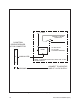
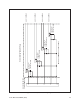
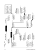
The AUX outputs are buffered to provide a continuous
10 VDC at 25 mA to drive small relays, lamps or some
other external device. Refer to Figures 16 and 17 for
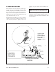
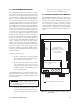
Figure 15. Jumper Settings, Receiver/Driver Mother Board
SW1
shown in the
"Short" position
P2
P1
BNC
CONNECTORS
37-PIN
AMP CONNECTOR
POWER INPUT
PC BOARD
COAXITRON SYSTEM 2000
RECEIVER
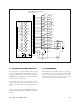
Latching
Momentary
JP1
JP2
JP3
JP4
AUX 1
AUX 2
AUX 3
AUX 4
AUXILLARY JUMPER
SETTINGS ON THE
COAXITRON RECEIVER
BOARD. JUMPERS ARE
SHOWN IN THE
OR "MODE".
MOMENTARY "POSITION"
**
boards, SW1 positions are
For Revision K (REVK)
shown above is the "Long"
position for REVK boards.
reversed; i.e., the position
**
examples of typical circuits used for auxiliary func-
tions.
Note: The preceding two paragraphs pertain to
Revision J or newer Receiver/Driver Mother boards.
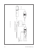
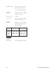
Figure 18 shows a typical connection using the latching
command to operate an AI700 or AI701 for auto iris or
manual iris operation. AUX 1 latches manual iris; AUX
2 latches auto iris.