INSTALLATION/OPERATION NVR300 Network Video Recorder C611M-C (3/06)
Contents Important Safety Instructions . . . . . . . . . . . . . . . . . . . . . . . . . . . . . . . . . . . . . . . . . . . . . . . . . . . . . . . . . . . . . . . . . . . . . . . . . . . . . . . . . . . . . . . . . . . .7 Product Overview . . . . . . . . . . . . . . . . . . . . . . . . . . . . . . . . . . . . . . . . . . . . . . . . . . . . . . . . . . . . . . . . . . . . . . . . . . . . . . . . . . . . . . . . . . . . . . . . . . . . .8 Description . . . . . . . . . . . . . . . . . . . . . . . . . . . .
Troubleshooting Guidelines . . . . . . . . . . . . . . . . . . . . . . . . . . . . . . . . . . . . . . . . . . . . . . . . . . . . . . . . . . . . . . . . . . . . . . . . . . . . . . . . . . . . . . . .72 Error Messages . . . . . . . . . . . . . . . . . . . . . . . . . . . . . . . . . . . . . . . . . . . . . . . . . . . . . . . . . . . . . . . . . . . . . . . . . . . . . . . . . . . . . . . . . . . . . . . . .74 Specifications . . . . . . . . . . . . . . . . . . . . . . . . . . . . . . . . . . . . . . . . .
List of Illustrations 1 2 3 4 5 6 7 8 9 10 11 12 13 14 15 16 17 18 19 20 21 22 23 24 25 26 27 28 29 30 31 32 33 34 35 36 37 38 39 40 41 42 43 44 45 46 47 C611M-C (3/06) Sample NVR300 Application . . . . . . . . . . . . . . . . . . . . . . . . . . . . . . . . . . . . . . . . . . . . . . . . . . . . . . . . . . . . . . . . . . . . . . . . . . . . . . . . . . . . . . . .9 Front View of NVR300 . . . . . . . . . . . . . . . . . . . . . . . . . . . . . . . . . . . . . . . . . . . . . . . . . . . . . . . . . . .
List of Tables A B C D E F G H 6 NVR300 Models . . . . . . . . . . . . . . . . . . . . . . . . . . . . . . . . . . . . . . . . . . . . . . . . . . . . . . . . . . . . . . . . . . . . . . . . . . . . . . . . . . . . . . . . . . . . . . . . .10 NVR300 Pages and Associated Operations . . . . . . . . . . . . . . . . . . . . . . . . . . . . . . . . . . . . . . . . . . . . . . . . . . . . . . . . . . . . . . . . . . . . . . . . . . . .29 Client PC System Requirements . . . . . . . . . . . . . . . . . . . . . .
Important Safety Instructions Observe the following warnings before installing and using this product: 1. Read these instructions. 2. Keep these instructions. 3. Heed all warnings. 4. Follow all instructions. 5. Do not use this apparatus near water. 6. Clean only with dry cloth. 7. Do not block any ventilation openings. Install in accordance with the manufacturer’s instructions. 8.
Product Overview This section provides an overview of the NVR300 network video recorder, software version 3.00.
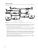
SAMPLE APPLICATION Figure 1 illustrates a sample scenario of an NVR300 application Integration of the NVR300 user interface with the VMX300 allows the NVR300 to operate as part of an entire system. NET350T NET4001A NET4001A DX9200HDDI NVR300 TCP/IP NETWORK CLIENT PC NET300T VMX CLIENT/SERVER VMX CLIENT Figure 1. Sample NVR300 Application NOTE: For information about the NET4001A, NET350T, NET300T, VMX300, and DX9200HDDI devices, consult the device-specific documentation.
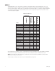
MODELS The NVR300 comprises a series of network video recorders based on the maximum number of supported PelcoNet devices: 16, 32, or 64. The network video recorders also vary based on the amount of internal storage space, the hard disk drive configuration, and the capability to connect to external storage units. Table A provides a list of NVR300 models. In the model number, a “J” designates a non-RAID system while an “R” designates an internal RAID system. An external RAID system has no letter.
FRONT VIEW Figure 2 illustrates the front view of the NVR300. LOCK (2 KEYS SUPPLIED) POWER LED HDD (HARD DISK DRIVE) LED HANDLE (2) FAN VENTILATION A. NVR300 WITH FRONT DOOR CLOSED HARD DISK DRIVE BAY POWER BUTTON OS 0 1 2 3 OPERATING SYSTEM (OS) HARD DISK DRIVE 4 5 6 DUMMY DATA STORAGE HARD DISK DRIVES (MAXIMUM OF SIX) B. NVR300 WITH FRONT DOOR OPEN Figure 2.
REAR VIEW Figure 3 illustrates the rear view of the NVR300. POWER INPUT (100-240 VAC ±10%) SCSI PORT (2)* 2 FOR FUTURE USE* USB PORT (2) COM 1 MONITOR ETHERNET PORT *AVAILABLE ON CERTAIN MODELS ONLY Figure 3. Rear View of NVR300 For detailed information about connections to the rear panel of the NVR300, refer to the Installation section of this manual.
Installation This section provides information about the tasks necessary to install the NVR300.
HARDWARE INSTALLATION MOUNTING THE NVR300 The NVR300 can be placed on a flat surface such as a desktop or can be mounted into an equipment rack. Information about mounting the NVR300 onto a desktop or into an equipment rack follows. Mounting the NVR300 onto a Desktop When mounting the NVR300 onto a desktop, ensure that rubber feet are installed on the NVR300. Position the unit to allow for cable and power cord clearance at the rear of the unit.
(4) SCREWS, 10-32 X 0.75-INCH, PAN HEAD (2 EACH SIDE) REAR-MOUNTING SUPPORT RAIL (6-8) SCREWS, 8-32 X 0.375-INCH, TRUSS HEAD (3-4 EACH SIDE) FRONT-MOUNTING SUPPORT RAIL CAGE NUT (8) SCREWS, 10-32 X 0.5-INCH, FLAT HEAD (4 EACH SIDE) NVR300 BRACKET (SIDE VIEW) (10) SCREWS, 10-32 X 0.25-INCH, PAN HEAD (5 EACH SIDE) TAPERED ENDS TOWARD REAR OF UNIT (4) SCREWS, 10-32 X 0.75-INCH, PAN HEAD (2 EACH SIDE) Figure 4.
INSTALLING HARD DISK DRIVES You must install the data storage hard disk drives supplied with the NVR300 unit. Note that the system drive is installed at the factory. WARNING: Handle the hard disk drives with care. Improper handling can easily damage the drives. In addition, prevent electrostatic discharge (ESD) damage to the hard disk drives by following ESD precautions. Always wear a grounding wrist strap that is connected to an approved grounding source when installing the hard disk drives.
CONNECTING THE NVR300 TO PERIPHERAL EQUIPMENT Connections of peripheral equipment to the NVR300 are made on the rear panel of the NVR300. Connections to the NVR300 include the following: • Keyboard, mouse, and monitor • Network equipment (for example, Ethernet switch) • DX9200HDDI video storage units (optional; only units without internal storage) • Power cord The following sections provide connection information.
Connecting to the Network To connect the NVR300 to the network, refer to Figure 7 and do the following: 1. Connect one end of an RJ-45 network cable to the 1000BaseT Ethernet port of the NVR300. 2. Connect the other end of the cable to the network (typically to an Ethernet switch). 2 ETHERNET SWITCH Figure 7.
POWERING ON THE NVR300 After the hard disk drives have been installed and the necessary connections have been made to the NVR300, power can be applied to the unit. To power on the NVR300, do the following: 1. Turn on the attached monitor. 2. On the rear panel of the NVR300, set the power supply ON/OFF switch to the ON position. 3. On the front panel of the NVR300, press the POWER button to power on the unit. The NVR300 boots.
IDENTIFYING THE NVR300 ON THE NETWORK To identify the NVR300 on the network, do the following: 1. Log in to Windows XP as a user by clicking the NVR300 icon. 2. Click the NVR300 Platform Admin icon to call up the NVR300 Platform Administrator screen. 3. On the NVR300 Platform Administrator screen, click the Network Settings button. 4. Make the necessary network changes. The Computer Name Changes dialog box appears. 5. In the “Computer name” text entry box, replace the default name with the desired new name.
CONFIGURING TCP/IP SETTINGS To configure TCP/IP settings, do the following: 1. Click the NVR300 Platform Admin icon to call up the NVR300 Platform Administrator screen. 2. On the NVR300 Platform Administrator screen, click the Network Settings button. 3. Double-click Local Area Connection. 4. Click Properties. The Local Area Connection Properties dialog box appears. 5. In the box listing the items used by the connection, double-click Internet Protocol (TCP/IP).
CONFIGURING ALERTS FOR AN EXTERNAL RAID NVR300 NOTE: The following information applies to external NVR300 RAID models only; and not to non-RAID models. If a hard disk drive fails or a communication error occurs within an external RAID configuration, the NVR300 allows three types of default notification to alert you of the failure or problem: • RAID Manager Messages.
Figure 11. Add Server 4. Enter the desired name for the NVR300 external RAID machine and the IP address of the NVR300 with the DX9200HDDI unit(s) attached. Click the OK button. A window showing the added HDDI(s) appears. Figure 12. HDDIs Added 5. The ACSGateway Config window should look similar to Figure 12. If you do not see anything listed on the right side of the window, double-click the newly-created server.
Figure 13. Event Notification 6. Checkmark the boxes shown in Figure 13. 7. Click the E-Mail Setting tab. The E-Mail Setting page appears. Figure 14.
8. Do the following: • Checkmark the Mail Notify box. • Enter in the Sender Name box the name that will appear as the sender in the e-mail sent for notifications. • Enter in the Sender E-mail Address box the e-mail address that will appear as the sender’s e-mail address in the e-mail sent for notifications. • Enter in the Recipient Name box the name of the person to whom the notifications will be addressed.
Figure 16. NetSend Setting (Second Page) 11. Click the OK button. The Event Notification window will close. Figure 17. ACSGateway Config Exit 12. Configuration is complete. Click Exit in the upper left. 13. To view the status of the external RAID, click the RAID Manager icon located on the desktop. An Internet Explorer window appears.
Figure 18. Allow Blocked Content 14. Click the ActiveX warning that appears at the top of the window. Then select Allow Blocked Content…. A security message appears. Figure 19. ActiveX Warning 15. Click the Yes button. The RAID Manager window appears. Figure 20.
16. Double-click Root, and then double-click the server to display attached RAID units, as shown. Figure 21. RAID Manager (Second Screen) 17. Double-click on the desired RAID unit to display the status. The RAID Manager Status window appears. Figure 22. RAID Manager Status 18. This window displays the status, brand, and size of each drive. After you finish, you can close this window. The RAID Manager software continues to monitor the external RAID unit(s).
Operation After the NVR300 has been installed, connected to the network, and powered up as discussed in the Installation section, the NVR300 is ready for operation. (For information about the setup and configuration of devices associated with NVR300 operation, that is, the PelcoNET devices and the VMX300 video management system, refer to the device-specific documentation.
NVR-PLAYBACK LINK A. NVR-PLAYBACK PAGE (REMOTE AVAILABILITY ONLY) NVR-STATUS LINK B. NVR-STATUS PAGE (REMOTE AVAILABILITY ONLY) Figure 23. (Part 1 of 2).
NVR-SETUP LINK C. NVR-SETUP PAGE (REMOTE AVAILABILITY ONLY) NVR-CONFIG LINK D. NVR-CONFIG PAGE (REMOTE AVAILABILITY ONLY) Figure 23 (Part 2 of 2).
START-UP TASKS To operate the NVR300, start-up tasks include the following: • Accessing the NVR300 user interface • Setting user access levels and associated passwords (performed by the system administrator or other qualified personnel only) • Logging in to the NVR300 (required only if user access levels and associated passwords have been set) Information about each of the start-up tasks follows.
Table C. Client PC System Requirements Hardware Requirements Processor: Intel® Pentium® 4, 2.4 GHz or higher Memory: 1 GB of RAM Graphics card: Standard PC graphics card that supports DirectX® 9.0 or higher Network Interface: Ethernet 10/100/1000 BaseT as needed Sound Card: Optional Software Requirements Windows® 2000, Windows XP Service Pack 2 (which includes Microsoft Virtual Machine that must be installed on the client PC) Microsoft Internet Explorer 6.0 (provided on NVR300 Resource CD) DirectX 9.
To set user access levels and associated passwords, do the following: 1. Open the NVR-Config page by clicking the NVR-Config link or the NVRConfig icon on the desktop. The NVR-Config page appears. Figure 24 shows the “Password settings” dialog box on the NVR-Config page. The dialog box allows you to set user access levels and associated passwords. Figure 24. NVR-Config Page—Password Settings Dialog Box 2. In the “Password settings” dialog box, do the following: a.
LOGGING IN TO THE NVR300 If you are required to log in to the NVR300, you must enter a user name and password. Before performing the procedure below, contact your system administrator for user name and password information. To log in to the NVR300, do the following: 1. Access the NVR300 (refer to the Accessing the NVR300 User Interface section for access information). A dialog box appears, allowing you to enter a user name and password (refer to Figure 25). Figure 25. User Name and Password Dialog Box 2.
OPERATIONAL TASKS When operating the NVR300, you can perform various tasks. The tasks that can be performed depend on the user access privileges that may have been assigned to you by the system administrator (refer to Table D for information about user access privileges).
Figure 26. NVR-Setup Page—Programmed Recordings Dialog Box NOTE: Figure 26 shows a Programmed Recordings dialog box that is empty, that is, the dialog box does not display a list of programmed recordings. Once recordings are programmed, they are listed in the dialog box as discussed later in this procedure. 2. Click the New button. The Add Recording dialog box appears (refer to Figure 27). Figure 27.
3. Program the configuration parameters. Refer to Table E for configuration guidelines. Table E. Recording Configuration Guidelines Configuration Parameter Configuration Guidelines Recording source Source for recording Add device manually From the drop-down box, select the PelcoNet device (IP address followed by PelcoNet device name, for example, 10.104.201.1 - PelcoNet 4001) that is to be the source of the recording. All PelcoNet devices known to the NVR300 are listed in the drop-down box.
Table E. Recording Configuration Guidelines (Continued) Configuration Parameter Configuration Guidelines Recording type Type of recording From the drop-down box, select one of the following recording modes: • Continuous recording—Allows the NVR300 to record continuously. Event recording—Allows the NVR300 to provide recording of only alarm input, motion alarm, video loss, and unified picture events including pre-alarm and post-alarm time as specified in the event recording section of the dialog box.
Table E. Recording Configuration Guidelines (Continued) Configuration Parameter Configuration Guidelines Event recording Alarm recording on If event recording is selected as the type of recording, select one or more of the following alarm event check boxes: • Alarm input(s)—Recording is based on the triggering of an external alarm sensor that is connected to the physical alarm input of the PelcoNet device.
Table E. Recording Configuration Guidelines (Continued) Configuration Parameter Configuration Guidelines Event recording (continued) Post-Alarm time If event recording is enabled, select the desired minimum amount of time of recording after the occurrence of an alarm event.
NOTE: If an X appears rather than a camera icon or clock icon, the NVR300 cannot record from that particular recording source. Refer to the Troubleshooting section for information. • The name of the video source is the unit name of the PelcoNet device followed by the camera name. A slash separates the unit name from the camera name. NOTE: If the PelcoNet device was not assigned a unit name, the IP address of the PelcoNet device is automatically displayed as the source name.
SCHEDULING A RECORDING NOTE: Service-level access privileges are required to schedule a recording. When programming a new recording or when editing a recording, you can schedule a recording on a weekly basis. To schedule a recording, perform the following: 1. Do either of the following: • If you are programming a new recording, click the Time button in the Add Recording dialog box. • If you are editing a recording, click the Time button in the Edit Recording Setup dialog box.
To select one or more particular time slots for additional days of the week, repeat steps a and b above. – Select an hourly time slot for all days of the week at once. To do so, click the appropriate hour selection button in the top row of the grid. The entire column in the grid is selected for that particular time slot and is shaded blue. For example, if you want recording to occur between 9:00 a.m. and 10:00 a.m., click the 9:00 hour selection button.
SEARCHING FOR A RECORDING Searching for a recording is performed from the NVR-Playback page remotely using the VMX300 or a client PC. You can search for a recording based on camera only or based on camera and a specific time period. To search for a recording, do the following: 1. Open the NVR-Playback page by clicking the NVR-Playback link. The NVR-Playback page appears. Figure 32 shows the recording search area of the NVR-Playback page.
b. In the “From time” text entry box, enter the desired time in hh:mm:ss military time format (hh = 2-digit hour numbered to 23, mm = 2-digit minute numbered to 59, and ss = 2-digit second numbered to 59). The default setting is 00:00:00. c. From the “To date” entry box, click the arrows button (< >) to enter a date. (The default setting is the current date of the NVR300.) The Calendar dialog box appears (refer to Figure 33).
• Stoptime—Displays the date and time the recording ended: – The date is displayed in mm/dd/yyyy format (mm = 2-digit month, dd = 2-digit day, and yyyy = 4-digit year). – The time is displayed in hh:mm:ss military time format (hh = 2-digit hour numbered to 23, mm = 2-digit minute numbered to 59, and ss = 2-digit second numbered to 59). NOTE: For the current track, the stoptime advances as the recording continues.
PLAYING A RECORDING WARNING: Because client PC resource availability varies it is strongly recommend that users play back one video stream at a time on a maximum of three client PCs to avoid potential performance issues. You can play a recording remotely using the VMX300 video management system or a client PC on the network. The playback capability of the NVR300 allows you to play recorded video and, if applicable, recorded audio. To play a recording, do the following: 1.
Resizing the Video Display Area The video display area displays the video content of the recording that is playing. You can resize the video display area by clicking either of the following links above the video display area: • 528x432—(Default setting) Resizes the video display area to 528 x 432 pixels (small). • 704x576—Resizes the video display area to 704 x 576 pixels (large).
Table F. Playback Controls Playback Control Function Time Back Moves the time slice backward in varying intervals depending on the interval set by the Zoom Out or Zoom In buttons. The default interval setting of the time slice is two hours. Time Forward Moves the time slice forward in varying intervals depending on the interval set by the Zoom Out or Zoom In buttons. The default interval setting of the time slice is two hours.
REPLAYING A RECORDING While a recording is playing, you can replay the recording from the start time in the following ways: • By using the appropriate playback controls on the NVR-Playback page. For detailed information about playback controls, refer to the Controlling Playback of a Recording section for detailed information. • By using the Replay recording command. For detailed information, refer to the Using the Replay Recording Command section that follows.
To select multiple recordings for deletion at one time, do the following: 1. In the recording selection area of the NVR-Playback page, select the recordings you wish to delete by doing either of the following: a. To select a group of adjacent recordings, click the first recording in the group and then hold down the SHIFT key and click the last recording in the group. b.
NOTE: Once a location is specified, all recordings you wish to save are saved to that location as MPEG files. You do not need to specify that location each time you save a recording. In addition, any snapshots that are taken will also be saved to that location as JPEG files. 4. Play the recording you wish to save (for instructions on how to play a recording, refer to the Playing a Recording section.
SELECT PATH BUTTON SNAPSHOT BUTTON Figure 39. NVR-Playback Controls Used to Take a Snapshot 3. If you wish to specify a location to which the snapshot should be saved, continue with steps 3a and 3b that follow; otherwise, omit those steps and proceed to step 4. a. Click the Select Path button. The “Path for saving MPEG/JPEG files” dialog box appears. b. Navigate to the location to which you wish to save the snapshot, and then click the Save button.
USING THE MPEG VIEWER TO PLAY MPEG FILES To play recorded video and also audio, if applicable, that was saved as an MPEG file as a result of saving a recording, use the MPEG Viewer software. (For information about saving a recording, refer to the Saving a Recording section.) The MPEG Viewer software is an executable application file named MPEGViewer.exe that can be opened from the NVR300 or can be downloaded from the NVR300 to any shared drive on the network.
• Clicking Open Folder opens the folder to which the MPEGViewer.exe file was saved. The MPEGViewer.exe file is highlighted in the folder. Double-clicking the file opens the MPEG Viewer application and allows you to play an MPEG file. For additional information, refer to the Playing an MPEG File section. • Clicking Close closes the “Download complete” dialog box. Playing an MPEG File To play an MPEG file using the MPEG Viewer, do the following: 1.
• Time indicators at the beginning and end of the progress indicator bar display the duration of the file in minutes:second format. The time indicators begin with 0:00 and end with xx:xx, where xx:xx indicates the duration of the file (for example, 15:12 indicates that the file is 15 minutes and 12 seconds in duration). • As the file plays, a time counter indicates the time that has elapsed since playback of the file began. The time is indicated in minutes:seconds format.
• Camera icon—Indicates that the recording is active; that is, the NVR300 is currently recording a stream generated by the PelcoNet device. • Clock icon—Indicates that the recording has been scheduled but is not currently active. When the recording becomes active, the clock icon changes to a camera icon. NOTE: If an X appears rather than a camera icon or clock icon, the NVR300 cannot record for that particular recording source. Refer to the Troubleshooting section for information.
System Upgrade This section provides information about the following: • Setting the software license to allow the NVR300 to support additional PelcoNet devices • Adding internal storage: • – Adding storage in a non-RAID system (applicable to NVR3xx-250 systems only: NVR316J-250 and NVR332J-250 – Adding storage in a RAID system (maximum of 1,500 GB internal storage) Adding external storage with up to two DX9200HDDI video storage units (maximum of 7,000 GB external storage) SETTING THE SOFTWARE LICE
4. In the Activation Code field, delete the copyright code and then enter the activation code: • If you are upgrading the license, enter the new activation code supplied with the new license. • If you are resetting the license, enter the activation code that is labeled on the NVR300 unit. 5. Click the Set button to set the activation code. The “License settings” dialog box displays the correct license configuration.
Step 2. Use Windows XP Disk Management to format the newly added storage drive (Disk 1). Using Windows XP Disk Management, format the newly added storage drive as follows: 1. Log in to Windows XP as Administrator. The default password is 2921981@$. The Windows XP desktop appears. 2. Open Windows XP Disk Management as follows: a. On the Windows XP desktop, right-click the My Computer icon and then click Manage. The Computer Management window appears. b.
ADDING EXTERNAL STORAGE WITH DX9200HDDI VIDEO STORAGE UNITS (For units with no internal storage only.) For expanded storage of NVR300 recordings, two SCSI ports are provided on the rear panel of NVR300 RAID systems (refer to Table A for a list of the applicable models). Each SCSI port can connect to a DX9200HDDI video storage unit. Each DX9200HDDI unit can contain a maximum storage capacity of 3,500 GB; therefore, a maximum of 7,000 GB of external storage can be added to the NVR300.
4. If the NVR300 is not already powered on, power on the unit by doing the following: a. On the rear panel of the NVR300, set the power supply ON/OFF switch to the ON position. b. On the front panel of the NVR300, press the POWER button to power on the unit. The NVR300 boots. During the boot process, the NVR300 splash screen appears, followed by the recovery boot option screen and the Windows XP boot screens. The Windows XP log-in screen then appears. Proceed to Step 2 that follows. Step 2.
d. Click the Next button. e. Confirm selection of Disk 2, and then click the Finish button. Both Disk 1 (NVR300 internal storage space) and Disk 2 (DX9200HDDI storage space) are on the same volume (Volume D) and the status is healthy. If you wish to add external storage with a second DX9200HDDI video storage section, continue with the next section.
Step 2. Use Windows XP Disk Management to extend storage volume of the NVR300 by adding disk space from the DX9200HDDI. Using Windows XP Disk Management, extend the storage volume (Volume D) of the NVR300 by adding disk space from the DX9200HDDI as follows: 1. Open Windows Disk Management as follows: a. On the Windows XP desktop, right-click the My Computer icon and then click Manage. The Computer Management window appears. b. In the left pane of the Computer Management window, locate the Storage item.
Service This section provides information about the following: • Recovering the system drive if the NVR300 operating system or NVR300 software is corrupted (applicable to NVR300 RAID systems only) • Replacing a failed data storage hard disk drive: – A data storage hard disk drive can be replaced in NVR3xx-500 systems: NVR316-500 and NVR332-500 (non-RAID) – A data storage hard disk drive can be replaced in an NVR300 RAID system NOTE: If license-related issues cause a problem, refer to Setting the Soft
5. Press the C key to reboot the NVR300. Proceed to Step 2 that follows. STEP 2. PERFORM MISCELLANEOUS TASKS. 1. If you are using DX9200HDDI external storage, extend the internal storage volume of the NVR300 by adding disk space from the DX9200HDDI. To do so, refer to the Adding External Storage with DX9200HDDI Video Storage Units section. 2. Configure the network settings as appropriate. For detailed information, refer to Network Settings Configuration in the Installation section. 3.
REPLACING A DATA STORAGE HARD DISK DRIVE IN A NON-RAID SYSTEM (NVR3xx-500 SYSTEMS ONLY) In NVR316-500 and NVR332-500 systems (non-RAID), the data storage hard disk drive is field replaceable. If the storage drive fails, you can replace it with a new drive. NOTE: All recordings on the failed storage drive are lost. Replacing a failed storage drive in an NVR3XX-500 GB system involves the following steps: 1. Replacing the failed storage drive with the new storage drive in the hard disk drive bay of the NVR300.
8. Power on the NVR300 by pressing the POWER button on the front panel of the unit. The NVR300 boots. During the boot process, the NVR300 splash screen appears, followed by the recovery boot option screen and the Windows XP boot screens. The Windows XP log-in screen then appears. 9. Lock the NVR300 front door. Proceed to Step 2 that follows. Step 2. Use Windows XP Disk Management to format the replacement storage drive. Using Windows XP Disk Management, format the replacement storage drive as follows: 1.
3. Open Windows XP Disk Management as follows: a. On the Windows XP desktop, right-click the My Computer icon and then click Manage. The Computer Management window appears. b. In the left pane of the Computer Management window, locate the Storage item. c. Under the Storage item, click Disk Management. 4. Extend the storage volume (Volume D) to the unallocated space in the new drive as follows: a. Right-click the storage volume, and then click Extend Volume….
6. Remove the failed storage drive from the carrier as follows: a. Observe that the drive is held in place by two retention clips on each side of the carrier. The two retention clips on each side of the carrier latch onto the holes on each side of the drive. b. Place the carrier containing the drive on a flat surface. c. Using a small screwdriver, carefully pull the retention clips on one side of the carrier away from the carrier while lifting the drive out of the carrier.
Troubleshooting This section provides information to help you determine the cause of a problem and suggested actions to correct the problem. • The Troubleshooting Guidelines section provides general troubleshooting tips. • The Error Messages section provides a list of NVR300 messages that indicate error conditions and suggested actions to correct the error conditions. TROUBLESHOOTING GUIDELINES Table G provides a list of NVR300 troubleshooting guidelines. Table G.
Table G. NVR300 Troubleshooting Guidelines (Continued) Problem Possible Cause Suggested Corrective Action Video loss condition—an X overlaid on a camera appears in the video playback area of the NVR-Playback page when attempting to play a recording. Coaxial cable connections to BNC connector on camera and PelcoNet device are faulty, or cable is defective.
ERROR MESSAGES Table H provides a list of NVR300 error messages. Table H. NVR300 Error Messages 74 Error Message Possible Cause Suggested Corrective Action SQL Error! Request for recordings failed The NVR300 cannot display a list of existing recordings due to an overload condition. Reduce system load by stopping recordings listed on the NVR-Setup page or by reducing resolution of the camera streams in the PelcoNet devices as appropriate.
Specifications ELECTRICAL / VIDEO Input Voltage 100-240 VAC +10%, 50/60 Hz, autoranging; reset feature enabled when power becomes unstable or interrupted Power Consumption 235 W maximum Operating System Microsoft® Windows® XP Professional Recording Rate 10 kbps-48/100 Mbps (recording rate will be affected during a rebuilding of the RAID array) Recording Frame Rate Up to 30 images per second (ips) per video stream, total of 960 ips for 32 streams Compression MPEG-2, MPEG-4 Hard Disk Drive Configu
Appendix. Automatic Data Replenishment (ADR) This appendix provides an overview of the Automatic Data Replenishment technology used by the NVR300. The appendix also provides setup instructions required for ADR functionality. ADR OVERVIEW When the NVR300 is connected to the PelcoNet NET350T transmission system equipped with local storage (CompactFlash card or a microdrive), ADR ensures video recording by the NVR300 despite temporary network failure or NVR300 downtime.
LOCAL STORAGE ADR can only copy video that exists on the CompactFlash storage device (card or IBM Microdrive™). Pelco recommends setting the NET350 to use the Ringbuffer (FIFO) storage method so it continually overwrites existing video. The storage “loop” has to be longer than the duration of the longest network outage to be protected against. Note that several settings affect the storage duration, so consult your local Pelco representative for storage estimation and the required size of the storage device.
Regulatory Notices This device complies with Part 15 of the FCC Rules. Operation is subject to the following two conditions: (1) this device may not cause harmful interference, and (2) this device must accept any interference received, including interference that may cause undesired operation. RADIO AND TELEVISION INTERFERENCE This equipment has been tested and found to comply with the limits of a Class A digital device, pursuant to Part 15 of the FCC Rules.
PRODUCT WARRANTY AND RETURN INFORMATION WARRANTY Pelco will repair or replace, without charge, any merchandise proved defective in material or workmanship for a period of one year after the date of shipment. Exceptions to this warranty are as noted below: • Five years on FR/FT/FS Series fiber optic products and TW3000 Series unshielded twisted pair transmission products. • Three years on Genex ® Series products (multiplexers, server, and keyboard).
Worldwide Headquarters 3500 Pelco Way Clovis, California 93612 USA USA & Canada Tel: 800/289-9100 Fax: 800/289-9150 International Tel: 1-559/292-1981 Fax: 1-559/348-1120 www.pelco.