I N S T A L L A T I O N IS310 Series Camclosure® Integrated Camera System C3429M-A (1/08)
Important Safety Instructions 1. Read these instructions. 2. Keep these instructions. 3. Heed all warnings. 4. Follow all instructions. 5. Do not block any ventilation openings. Install in accordance with the manufacturer’s instructions. 6. Do not install near any heat sources such as radiators, heat registers, stoves, or other apparatus (including amplifiers) that produce heat. 7. Only use attachments/accessories specified by the manufacturer. 8.
Regulatory Notices This device complies with Part 15 of the FCC Rules. Operation is subject to the following two conditions: (1) this device may not cause harmful interference, and (2) this device must accept any interference received, including interference that may cause undesired operation. RADIO AND TELEVISION INTERFERENCE This equipment has been tested and found to comply with the limits of a Class B digital device, pursuant to Part 15 of the FCC Rules.
Description The 310 Series Camclosure® integrated camera system is a track-light design that mounts to a wall or ceiling. The system incorporates a camera and lens package into a small, unobstructive, medium-security enclosure designed for areas subject to vandalism. The system is quick and easy to install in a variety of indoor or outdoor applications.
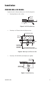
Installation PREPARE WALL OR CEILING Prepare the wall or ceiling according to one of the following options. • Mounting directly to wall or ceiling WALL OR CEILING Figure 1. Wall/Ceiling Mounting • Mounting to a 4S electrical box with 404 plaster ring 4S ELECTRICAL BOX WALL OR CEILING 404 PLASTER RING ICS310-AP ADAPTER PLATE (NOT SUPPLIED) 6-32 X 0.50 SECURITY SCREW (SUPPLIED WITH ADAPTER PLATE) Figure 2.
• Mounting to a 2-gang electrical box 2-GANG ELECTRICAL BOX WALL OR CEILING ICS310-AP ADAPTER PLATE (NOT SUPPLIED) 6-32 X 0.50 SECURITY SCREW (SUPPLIED WITH ADAPTER PLATE) Figure 4. Mounting to a 2-Gang Electrical Box CONNECT VIDEO AND POWER 1. Some indoor installations do not require a heater. If the installation does not require a heater, disconnect the heater wiring. a. Remove the cover with the supplied 1/8-inch hollow screwdriver bit. b.
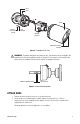
BASE VENT COVER PHILLIPS PAN HEAD SCREW LOCK WASHER CAMERA MODULE TAMPER-RESISTANT SCREWS Figure 5. Exploded Parts View WARNING: To prevent damage to the camera or lens, the camera must be installed in the proper hole of the mounting bracket (refer to Figure 6). If the camera is not installed in the correct hole, the window of the enclosure may be forced against the lens. MOUNT CAMERA HERE DO NOT USE Figure 6. Camera Mounting Holes ATTACH BASE 1.
ADJUST ENCLOSURE 1. Turn on power to the camera and monitor. 2. Release one or both locking rings, and swivel the enclosure until the angle of the camera is correct (refer to Figure 7). 3. Tighten the locking rings. LOCKING RINGS Figure 7. Adjusting Enclosure Position 4. If you have a varifocal lens, remove the cover with the supplied 1/8-inch hollow screwdriver bit. WARNING: Heater elements could be hot! When camera power is on, use caution when adjusting the camera. This applies to all models. 5.
DN/CH SERIES ADJUSTMENTS Refer to Figure 9 to adjust the IS310-DN or IS310-CH model. Figure 9. Adjusting the IS310-DN/CH Series Camclosure SWITCH SETTINGS Locate the DIP switch. Then set the switches for your installation. SW4-1: Auto Gain Control The automatic gain control (AGC) adjusts the image automatically to compensate for changes in light levels. Set SW4-1 to ON to enable AGC. Set it to OFF to disable AGC. The default setting is ON.
Set to SW4-4 ON to enable flickerless operation. The camera will remove the effects of flickering and the shutter speed will be set to 1/120 (NTSC) or 1/100 (PAL). Set to SW4-4 OFF to disable flickerless operation. This is the default setting. NOTE: If you enable flickerless operation, you should use AC line lock for best results. SW4-5: Auto White Balance/Manual White Balance Auto white balance (AWB) is enabled by default (OFF). To manually set and lock the white balance: 1. Set SW4-5 to OFF. 2.
Adjusting Vertical Phase You may need two people when synchronizing the cameras: one at the camera, the other at the monitor to observe the vertical roll and the effect of any camera adjustments. To synchronize the cameras: 1. Choose a reference camera to which all other cameras will be phased. 2. Select the camera to synchronize. Use buttons SW1 and SW2 to synchronize the camera to the reference camera (refer to Figure 9 on page 9). SW1 increases vertical phase; SW2 decreases vertical phase. 3.
DAY/NIGHT OPERATION NOTE: This section only applies to DN model cameras. DN model cameras regularly check the brightness level of the field of view to determine when to switch between day (color) and night (black-white) operation. Actual brightness threshold levels are affected by camera angle, amount of zoom, field of view, lens, and type of lighting. The switching process lasts from 7-10 seconds. RISING LIGHT LEVEL COLOR MODE 1.5 lux B-W MODE COLOR MODE 3.
DW/CW SERIES (WIDE DYNAMIC RANGE) ADJUSTMENTS Refer to Figure 11 to adjust the IS310-DW or IS310-CW model. SW1 DEFAULT SWITCH POSITION R7 Figure 11. Adjusting the IS310-DW/CW Series Camclosure SWITCH SETTINGS Locate the DIP switch and then set the switches for your installation. SW1-1: Video Format Set SW1-1 to ON for NTSC. Set it to OFF for PAL. The default setting is ON. SW1-2: Line Sync When multiple cameras are connected to the same switching device, vertical roll may occur on the monitor.
SW1-4: Auto White Balance/Manual White Balance Auto white balance (AWB) is enabled by default (ON). To manually set and lock the white balance: 1. Set SW1-4 to ON. 2. Hold a white background in front of the lens until the video is all white. 3. While holding the background in place, set SW1-4 to OFF. A green block and a white block alternate briefly on the video image until the manual white balance (MWB) process is complete.
SW1-8: Day/Night Operation (DW models only) NOTE: On CW models, SW1-8 is unused and does not affect camera operation. DW model cameras regularly check the brightness level of the field of view to determine when to switch between day (color) and night (black-white) operation. Use SW1-8 to set the general light levels at which the camera will automatically switch. Set SW1-8 to ON (dark) to use standard thresholds to switch between color and black-white operation. This is the default setting.
AUTO IRIS LEVEL ADJUSTMENT The electronics of the IS310-DW and IS310-CW Series Camclosures automatically adjust the camera to the auto iris. Auto iris level adjustments are not necessary. VERTICAL PHASE ADJUSTMENT NOTES: • Use this procedure for 24 VAC operation only. • When adjusting vertical phase, line sync (SW1-2) must be set to ON for AC line lock. When using more than one camera power supply, a brief vertical roll may occur on the monitor when switching from one camera to another.
Service Connector The IS310 Series Camclosure integrated camera system includes a service connector that outputs camera video. Use it at the installation site to set up the field of view and focus the camera. SERVICE CONNECTOR Figure 13. Service Connector Pelco offers two optional items that plug directly into the service connector: CST150 compact field tool and IS-SC cable. • The optional CST150 compact field tool has a 3-foot (0.9 m) cable and microdisplay for viewing camera video.
Specifications General Pan/Tilt Adjustment Pan Tilt Construction Finish Environment Operating Temperature Heater Unit Weight Electrical Input Voltage Power Consumption Video Connector Manual 180° 180° Aluminum base and cover, steel camera mounting bracket Gray polyester powder coat Low temperature, indoor/outdoor -50° to 122°F (-46° to 50°C); de-ices to -10°F (-23°C) Turns on at 50°F (10°C) and off at 80°F (27°C) 1.45 lb (6 kg) 12 VDC or 24 VAC, ±10% 13 W or less BNC UTP wires 4.26 (10.82) 7.14 (18.
PRODUCT WARRANTY AND RETURN INFORMATION WARRANTY Pelco will repair or replace, without charge, any merchandise proved defective in material or workmanship for a period of one year after the date of shipment. Exceptions to this warranty are as noted below: • • • • • • • • • • • • • • Five years on fiber optic products and TW3000 Series unshielded twisted pair (UTP) transmission products. Three years on Spectra® IV products. Three years on Genex® Series products (multiplexers, server, and keyboard).
Worldwide Headquarters 3500 Pelco Way Clovis, California 93612 USA USA & Canada Tel: 800/289-9100 Fax: 800/289-9150 International Tel: 1-559/292-1981 Fax: 1-559/348-1120 www.pelco.