® MPT9500 Series Transmitter/ Controller Installation/ Operation Manual C535M-B (8/98) Pelco • 3500 Pelco Way • Clovis, CA 93612-5699 USA • www.pelco.
CONTENTS Section Page 1.0 GENERAL .................................................................................................. 5 1.1 IMPORTANT SAFEGUARDS AND WARNINGS ............................... 5 2.0 DESCRIPTION .......................................................................................... 6 2.1 MODELS ............................................................................................ 6 3.0 INSTALLATION .......................................................................
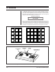
LIST OF ILLUSTRATIONS Figure 1 2 3 4 5 6 7 8 Page Multiple Camera Coaxitron® System .................................................. 7 RS-485 Duplex Control System (PTZ Control and Alarm Reporting) 8 MPT9500 Rear View and RS-485 Serial Port Pin Out ....................... 8 RS-485 Simplex System (PTZ Control Only) ..................................... 9 Combination Coaxitron® and RS-485 (Simplex) System ................... 9 MPT9500 Keypad Layout ..........................................................
(This page intentionally left blank.
1.0 GENERAL 1.1 IMPORTANT SAFEGUARDS AND WARNINGS Prior to installation and use of this product, the following WARNINGS should be observed. 1. Installation and servicing should only be done by qualified service personnel and conform to all local codes. 2. Unless the unit is specifically marked as a NEMA Type 3, 3R, 3S, 4, 4X ,6 or 6P enclosure, it is designed for Indoor use only and it must not be installed where exposed to rain and moisture. 3. Only use replacement parts recommended by Pelco. 4.
2.0 DESCRIPTION The MPT9500 Transmitter/Controller provides control in Vertical Interval Signaling (standard or extended Coaxitron®) and RS-485 formats. The transmitter/controller supports control options of the CX9500, CX9504 and CX9000 Series Coaxitron® receiver/drivers, as well as Intercept® and Legacy® Series receiver/drivers.
3.0 INSTALLATION 3.1 THE VIS (COAXITRON®) CONTROL SYSTEM The operating distance for the Vertical Interval Signaling (VIS) system is probably the most crucial installation parameter. For a VIS control system, the maximum loss allowed across the coax is 4 dB at 1 MHz. The actual distance for a system without equalizing amplifiers can be calculated by the following formula. Distance =4 dB / Loss of the Coax Cable and any Splices Terminations for the video must be supplied at the controller end of the coax.
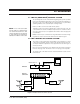
3.3 CONNECTING TO THE RECEIVERS The rear panel view and pin out for the 6 pin modular cable is shown in Figure 3. Refer to Figures 4 and 5 for additional system configurations. PROGRAMMING MONITOR KEEP PARALLEL CONNECTIONS INTO RECEIVERS VERY SHORT NO “T” CONNECTIONS CX9504 RXD (–) RXD (+) TXD (–) TXD (+) 1 TXD (–) 2 TXD (+) 3 GND 4 GND 5 RXD (–) 6 RXD (+) CX9504 RXD (–) RXD (+) TXD (–) TXD (+) RXD (–) RXD (+) TXD (–) TXD (+) THE LAST RECEIVER/DRIVER MUST BE TERMINATED WITH 120 OHMS.
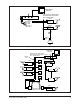
PROGRAMMING MONITOR KEEP PARALLEL CONNECTIONS INTO RECEIVERS VERY SHORT; NO “T” CONNECTIONS. CX9504 1 TXD (–) 2 TXD (+) 3 GND 4 GND 5 RXD (–) 6 RXD (+) RXD (–) RXD (+) CX9504 RXD (–) RXD (+) RXD (–) RXD (+) Figure 4. RS-485 Simplex System (PTZ Control Only) PROGRAMMING MONITOR KEEP PARALLEL CONNECTIONS INTO RECEIVERS VERY SHORT; MPT9500 NO “T” CONNECTIONS. TWISTED PAIR MANUAL SWITCHER COAX CX9504 COAX CX9504 CX9500 CX9504 CX9500 COAX MICROWAVE REMOTE RECEIVER CX9504 Figure 5.
4.0 OPERATION The MPT9500 operates in one of three modes: Coaxitron® Standard (15-bit protocol), Coaxitron® Extended (32-bit protocol) and RS-485. Which mode is usable depends upon receiver configuration; however, upon power up or reset the transmitter will wake up in the default Coaxitron® “extended commands” mode. The keyboard display will indicate “EXT CXTRN” when in this mode.
4.1 SELECTION OF STANDARD COAXITRON® To select the Standard Coaxitron® mode of operation, press the number “1” key and then press the “COAX RECV” key. The default keyboard display will read “STD CXTRN”. This mode will operate the standard 15 bit Coaxitron® receivers and their preset commands. 4.2 SELECTION OF RS-485 CONTROL To switch from Coaxitron® to RS-485 mode, enter the number of the desired receiver address (such as “1”) and press the “RECV ADDRS” key.
Enter whatever number you desire or need and press the “PRESET SET” key. The keyboard display will show: PGM LABEL and the following screen will pop up on the monitor: Flashing Cursor EDIT PRESET LABEL → → CLEAR TO EXIT USE JOYSTICK UP DOWN CHAR SET → CHAR POSITION F2 TO SEND LABEL → giving you the programming information you need to create a preset label on the monitor.
and on the monitor the following screen will appear: → → SET PRESET? JOYSTICK F1 TO EXIT YES ❊ NO Joystick operation for Standard Coaxitron® mode is the same as that already described for Extended and RS-485 mode. If the PRESET SET key has been hit accidentally and you wish to exit, use the joystick to position the * character in the “NO” row and press the F1 key. If setting a preset was really intended then make sure the * character is positioned in the “YES” row and press the F1 key.
Hitting F3 PREV would take you back to the previous page. PRE stands for preset address (1-32). DWL stands for dwell rate entered in seconds (1-99). During the execution of a preset tour, dwell rate is NOT the amount of time spent at any one camera viewing position or preset address. Dwell rate is defined as the amount of time in seconds between the moment the pan/tilt begins moving to the current preset and the next preset in the tour. An example might make this clearer.
4.3.6 Programming Lens Speed This feature is only available on receivers that support programming lens speed. To program lens speed, press the number 8 key followed by the F1 key. The keyboard display should be as follows: ZOOM SPD The following screen will appear on the monitor. ENTER ZOOM SPEED 1 - 4 and PUSH SELECT F1 TO EXIT The numerical range 1 - 4 is called the “speed spread”. A value of “1” selects the slowest and a value of “4” selects the fastest lens speed.
4.3.9 Programming Auxiliary Functions This feature will operate only on receivers that support this option. This programming feature in the new receivers will allow the auxiliary outputs (1-8) to be either latching or momentary. To enter this program mode press the number 6 key followed by the F1 key.
4.3.10.2 Pattern End Point If the pattern time is less than the maximum allowed, simply end the pattern sequence by pressing the number 2 key and then press the F1 key. This will end the pattern routine. 4.3.10.3 Running a Pattern To activate the pattern, press the number 3 key followed by the F1 key. The pattern will run indefinitely. To end the pattern send any PTZ command to the receiver. 4.3.11 Zones Zones are specific pan areas to which identifying labels can be attached.
4.3.12 Time (MPT9500TD Only) The MPT9500 is equipped with a time clock for specific functions requiring reference to time and date. 4.3.12.1 Set Time (MPT9500TD Only) To set the time, press the number 1 key followed by the F2 key. The keyboard display will be as follows: YEARS and on the monitor will appear the following: ENTER YEAR and PUSH SELECT F1 TO EXIT Enter a value for the year and momentarily press SELECT.
5.0 SPECIFICATIONS ELECTRICAL Input Voltage: Power Consumption: Control Method: Standard Baud Rates: NOTE: Operating distances are calculated and based on typical performance. The actual calculations are explained in the installation section of this manual and should be done for each application prior to installation. (50/60 Hz) 120, 230 VAC 12 watts Coaxitron® VIS 4-wire RS-485 VIS 1 MHz RS-485 2400 baud Command Error Rates: DUPLEX 0% SIMPLEX 2% Input Video Level: 0.5 to 1.
6.0 WARRANTY AND RETURN INFORMATION WARRANTY Pelco will repair or replace, without charge, any merchandise proved defective in material or workmanship for a period of one year after the date of shipment. Exceptions to this warranty are as noted below: • Five years on FT/FR8000 Series fiber optic products. • Three years on Genex® Series products (multiplexers, server, and keyboard).