® KBD9000 Transmitter/ Controller Installation/ Operation Manual C551M (4/98) Pelco • 3500 Pelco Way, Clovis • CA 93612-5699 USA • www.pelco.
CONTENTS Section Page 1.0 GENERAL .................................................................................................. 3 1.1 IMPORTANT SAFEGUARDS AND WARNINGS ............................... 3 1.2 REGULATORY NOTICES .................................................................. 4 1.3 UNPACKING INSTRUCTIONS .......................................................... 4 2.0 DESCRIPTION .......................................................................................... 5 2.1 MODELS ...
1.0 GENERAL 1.1 IMPORTANT SAFEGUARDS AND WARNINGS Prior to installation and use of this product, the following WARNINGS should be observed. 1. Installation and servicing should only be done by Qualified Service Personnel and conform to all Local codes. 2. Unless the unit is specifically marked as a NEMA Type 3, 3R, 3S, 4, 4X, 6, or 6P enclosure, it is designed for indoor use only and it must not be installed where exposed to rain and moisture. 3. Only use replacement parts recommended by Pelco.
1.2 REGULATORY NOTICES NOTE: This equipment has been tested and found to comply with the limits of a Class B digital device, pursuant to part 15 of the FCC rules. These limits are designed to provide reasonable protection against harmful interference in a residential installation. This equipment generates, uses, and can radiate radio frequency energy and, if not installed and used in accordance with the instructions, may cause harmful interference to radio communications.
2.0 DESCRIPTION The KBD9000 Transmitter/Controller is a desk top unit that provides up to 16 remote control functions. It operates without the need for control cables other than for a dedicated video cable for the normal transmission of a remote camera signal to the local monitoring and control position. Coaxitron® control lends itself to applications where short-to-medium distances are involved and where equalization of cable losses is not required. Check your receiver/driver manual for active functions.
KBD9000 provides the following standard functions: 1. Pan/Tilt 2. Lens Control — Zoom, iris, and focus 3. Camera power (on/off) The KBD9000 does not have preset capabilities, but it will work with receivers capable of doing presets. 2.1 MODELS KBD9000 Desktop Coaxitron® transmitter/controller with pan & tilt and zoom lens control. 120 VAC input. KBD9000-X Same as the KBD9000 except 230 VAC input. (CE) 2.
3.0 INSTALLATION 3.1 POWER No power on/off switch is provided. To apply power: insert the wall mount transformer plug into the 12 VAC power jack in the rear panel and insert the wall mount transformer into a 120 VAC power source (230 VAC with KBD9000-X). 3.2 VIDEO INPUT NOTE: Refer to Table A for the type of video coaxial cable to use. Connect a good grade of video coaxial cable from the Coaxitron® receiver or manual video switcher to the video “IN” BNC connector on the rear panel of the KBD9000.
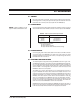
MONITOR (TERMINATED) COAXIAL CABLE VIDEO SIGNAL COAXITRON® RECEIVER MULTICONDUCTOR CABLE KBD9000 Figure 1. Basic KBD9000 Configuration MONITOR (TERMINATED) COAXIAL CABLE VIDEO SIGNAL COAXITRON® RECEIVER MULTICONDUCTOR CABLE MANUAL SWITCHER KBD9000 VIDEO SIGNAL COAXITRON® RECEIVER MULTICONDUCTOR CABLE Figure 2.
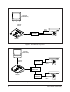
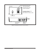
RECEIVER VIDEO CABLE INPUT FROM CAMERA RECEIVER RECEIVER VIDEO CABLE OUTPUT TO KBD9000 RECEIVER CONTROL OUTPUT TO PAN AND TILT/LENS (AMP SERIES CPC OUTPUT CONN) 24/120/230 VAC DC POWER INPUT HiZ 75Ω IN INPUT FROM RECEIVER OUT OUTPUT TO MONITOR Figure 3.
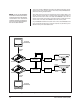
The Figure 4 drawing, KBD9000 Configuration with Multiple Transmitter and Receivers, shows a more complex system. In this example, multiple KBD9000 transmitters are controlling multiple receivers. NOTE: All but the last KBD9000 transmitter and associate switcher must be looping and unterminated. Transmitters and associated switchers should be physically adjacent to prevent signal deterioration due to cable mismatch.
4.0 OPERATION In general, all operating controls on the KBD9000 are self-explanatory. See Section 4.2, KBD9000 CONTROLS, for more information about each control function. 4.1 FUNCTIONAL CIRCUIT DESCRIPTION The basic functional concept of a Coaxitron® system feeds 15 control pulses in a reverse direction from the KBD9000 control transmitter to the receiver located near each camera station.
As an example, assume that the operator switches to manual iris control and proceeds to open the iris excessively. The result can be a complete loss of control. Within 20 to 40 seconds, camera power is automatically removed (assuming this feature exists) and auto iris is reinstated. 4.2 KBD9000 CONTROLS Refer to Figure 5. KBD900 Control Buttons to better understand the KBD9000 controls.
5.0 TROUBLESHOOTING If you experience operating problems with either the receiver or the KBD9000, first check all receiver fuses and voltage readings to make sure they are in working order. The Pelco CX900TLC Local Test Board Plug-in Module can be utilized to verify that receiver functions and accessories are operational. There is little that can be done without the aid of an oscilloscope. We recommend you contact your local dealer or our Customer Service Department for assistance.
6.0 MAINTENANCE The KBD9000 is engineered to provide years of reliable service. Regularly scheduled maintenance is not required. Clean the outer surface of the KBD9000 with a nonabrasive cleaning cloth and antistatic cleaner. Be sure not to get any cleaner inside the KBD9000 case.
7.0 SPECIFICATIONS ELECTRICAL Input Voltage: Power Consumption: Connectors: Input Impedance: Control Method: Pulse Amplitude: Input Video Level: System Bandwidth: 12 VAC from a 120 VAC, 60 Hz wall transformer provided with unit (230 VAC, 50 Hz with KBD9000-X) 2.5 vA Two video BNC connectors (video input and output) 75 ohms or high impedance (Hi Z), switchable 15-pulse train (pulse width modulated) superimposed on the video signal during the vertical blanking interval by the KBD9000 control transmitter.
8.0 WARRANTY AND RETURN INFORMATION WARRANTY Pelco will repair or replace, without charge, any merchandise proved defective in material or workmanship for a period of one year after the date of shipment. Exceptions to this warranty are as noted below: • Five years on FT/FR8000 Series fiber optic products. • Three years on Genex® Series products (multiplexers, server, and keyboard).