
Installation Manual

C256M-C (4/99)
PM2000/PM2010
Universal Ceiling/Pedestal Mount
300 W. Pontiac Way,
Clovis, CA 93612-5699
USA
In North America & Canada:
Tel (800) 289-9100
FAX (800) 289-9150
DataFAX (800) 289-9108
International Customers:
Tel (1-559) 292-1981
FAX (1-559) 348-1120
DataFAX (1-559) 292-0435
Pelco Online
http://www.pelco.com
®
IMPORTANT SAFEGUARDS AND WARNINGS
Observe the following warnings before installing and using this product.
1. Installation and servicing should be done by qualified installation and service personnel only.
2. Installation should be done according to all local and national electrical and mechanical
codes, using only approved materials.
3. Use only installation methods and materials capable of supporting four times the maxi-
mum weight of the equipment to be mounted.
4. Use stainless steel hardware to fasten the mount to outdoor surfaces.
5. To prevent damage from water leakage when installing a mount outdoors, apply sealant
around the bolt holes between the mount and the mounting surface.
The product and/or manual may bear the following marks:
Please thoroughly familiarize yourself with the information in this manual prior to installation
and operation.
DESCRIPTION
The PM2000 and PM2010 universal ceiling/pedestal mounts are designed for use with
medium- to heavy-duty scanners and pan and tilt units and will safely support loads up to 125
pounds (57 kg). Using two or more ST1 support struts with the PM2000 can add stability to the
mount in high wind conditions. These universal mounts will accept the AH1000 and AH2000
adjustable heads for ceiling or pedestal mounting of camera enclosures or a PA2000 mount
adapter for use with the Legacy
®
integrated positioning system. Both mounts are constructed
of aluminum and have a gray polyester powder coat finish.
Models
PM2000 Universal ceiling/pedestal mount for use with medium- or heavy-duty scan-
ners and pan and tilt units; 24 inches (61.0 cm) in height
PM2010 Same as PM2000, except 10 inches (25.4 cm) in height
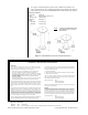
INSTALLATION
1. Determine the correct positioning of the ceiling/pedestal mount. For Legacy
®
and
medium-duty scanner and pan and tilt installations, the 8.5-inch (21.6 cm) diameter end
will be attached to the mounting surface. For heavy-duty pan and tilt installations, the 6.0-
inch (15.2 cm) diameter end will be attached to the mounting surface.
2. Using the PM2000 or PM2010 universal ceiling/pedestal mount as a template, drill holes
into the mounting surface.
3. Attach the ceiling/pedestal mount to the mounting surface with 5/16-inch diameter stain-
less steel fasteners (not supplied). To prevent water damage if installed outdoors, seal
the bolt holes with appropriate sealant (not supplied). Apply the sealant around the bolt
holes between the ceiling/pedestal mount and the mounting surface.
4. Attach ST1 support struts to the PM2000 mount as required for high wind conditions.
5. Refer to the AH1000/AH2000 manual for instructions to attach an adjustable head to the
ceiling/pedestal mount.
This symbol indicates that danger-
ous voltage constituting a risk of
electric shock is present within this
unit.
This symbol indicates that there are
important operating and mainte-
nance instructions in the literature
accompanying this unit.
CAUTION:
RISK OF ELECTRIC SHOCK.
DO NOT OPEN.
LISTED
U
L
®
CAUTION:
Make
certain the mounting
surface is capable of
supporting the full load of the
ceiling/pedestal mount, scanner
or pan and tilt, and camera/
enclosure.