
user manual

4 Pelco Manual C655M (6/99)
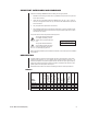
APPLICATION EXAMPLES
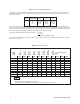
Table A contains examples of products and the number of units that can be powered by
each power supply, and is based on the vA rating of each product.
Table A. Product Capacity
Power Supply Model
Product MCS4-2E MCS8-5E MCS16-10E MCS16-20E
CCD Camera (12 vA maximum) 4 8 16 16
DF5/DF5S with camera (3 vA) 4 8 16 16
DF8A/PDF8 (12 vA maximum) 4 8 16 16
Indoor Spectra
®
(30 vA) 1 4 8 16
Esprit™ (50 vA) — 2 4 8
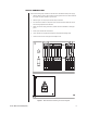
INSTALLATION
The following items are supplied:
1 MCS*E Series Power Supply
2 Spare fuses
2Wire nuts
To install an MCS Series power supply, perform the following steps:
1. Decide where to install the unit.
2. Open the lid on the unit by removing the 8-32 Phillips screw.
3. Drill holes in the mounting surface. Use the unit as a template.
4. Attach the unit securely with four fasteners (not supplied) of the appropriate length.
You can use fasteners up to 5/16-inch (0.80 cm) in diameter.
5. Punch out the necessary knockouts. (There are six knockout holes on the top and two
on the bottom.)
6. Install 1/2-inch (1.27 cm) or 3/4-inch (1.91 cm) conduit fittings where necessary (con-
duit fittings not provided).
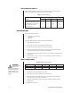
INPUT CONNECTIONS
WARNING:
Pelco will not be
liable for any
damages resulting from
incorrect wiring or im-
proper loading of an
MCS*E Series power
supply.
Table B. Main Fuse Value Table
Fuse Location MCS4-2E MCS8-5E MCS16-10E MCS16-20E
Main 1 A 1.6 A 3 A 5 A
Individual Output 1 A 3 A 3 A 3 A
1. Verify that the on/off switch inside the box is OFF.
2. Remove the high voltage compartment panel inside the box.
3. Attach the 120 input wires to the flying leads in the compartment with the supplied
wire nuts (Brown – AC Line; Blue – AC Neutral).
4. Attach the input ground wire to the stud inside the compartment with the supplied
washer and nut.
5. Replace the access panel.