INSTALLATION MANUAL Pressurized Spectra III™ Series ® Fiber Optic Models C2485M-A (1/05)
C2485M-A (1/05)
Welcome Thank you for purchasing Pelco’s Pressurized Spectra III™ Series dome system with feedthrough for fiber optic modules with an ST-type connector. Your new system provides ultimate protection of the camera optics and electronics from moisture, corrosive gases, and airborne contaminants. This manual is designed to be a reference tool for the installation of your system. For best results and ease of installation, the dome system should be assembled, pressurized, and tested before installation.
Preinstallation 1 Install the fiber optic module: Open the hinged door to the back box by pushing the tab lock towards the wall of the unit and lifting the door open. Remove the plug from the 16-pin connector. Install the module in the 16-pin connector. Secure the module to the circuit board standoff using the screw and lock washer provided. Connect the back box fiber optic connector to the mating connector on the module.
Install the dome drive: a. Set the DIP switches located on the side of the dome drive. Refer to the labels located on the top of the dome drive or to the Quick Start Guide shipped with the dome drive. SW1 SW2 SW3 b. Line up the blue (A) and red (B) tabs with the blue (A) and red (B) labels. c. Push in on the tabs. Insert one side and then the other side. Continue pushing until both sides of the dome drive click into place. 6 Install the lower dome: a.
Site Installation 1 2 Feed a fiber optic cable (not supplied) and the supplied wiring harness into the front of the mount and out the back of the mount. Connect the wires as required. Refer to Tables A, B, and C for cable and wiring information. Fasten the mount to the mounting surface. Refer to the instructions supplied with the mount.
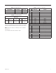
Table C. Configuration of Wire Harness Table A. Fiber Optic Cable Types Spectra Model Cable Type Connector Single mode (PRS models) 9/125 µm cable ST type Multimode (PRM models) 62.5/125 µm cable ST type Table B. 24 VAC Wiring Distances Wire Gauge Total VA 20 (0.5 mm2) 18 (1.0 mm2) 16 (1.5 mm2) 16 (2.5 mm2) 75 37 ft (11 m) 60 ft (18 m) 95 ft (29 m) 153 ft (46m) NOTE: These are the recommended maximum distances for 24 VAC applications and are calculated with a 10 percent voltage drop.
World Headquarters 3500 Pelco Way Clovis, California 93612 USA USA & Canada Tel: 800/289-9100 Fax: 800/289-9150 International Tel: 1-559/292-1981 Fax: 1-559/348-1120 www.pelco.