I N S T A L L A T I O N Rack Mount Chassis RK5000PS-5U For Endura Modules C1615M-A (9/05)
Contents Regulatory Notices . . . . . . . . . . . . . . . . . . . . . . . . . . . . . . . . . . . . . . . . . . . . . . . . . . . . . . . . . . . . . . . . . . . . . . . . . . . . . . . . . . . . . . . . . . . . . . . . . . . .3 Before You Begin . . . . . . . . . . . . . . . . . . . . . . . . . . . . . . . . . . . . . . . . . . . . . . . . . . . . . . . . . . . . . . . . . . . . . . . . . . . . . . . . . . . . . . . . . . . . . . . . . . . . .4 Parts List . . . . . . . . . . . . . . . . . . . . . . . . . .
Regulatory Notices This device complies with Part 15 of the FCC Rules. Operation is subject to the following two conditions: (1) this device may not cause harmful interference, and (2) this device must accept any interference received, including interference that may cause undesired operation. RADIO AND TELEVISION INTERFERENCE This equipment has been tested and found to comply with the limits of a Class A digital device, pursuant to Part 15 of the FCC Rules.
Before You Begin Please familiarize yourself with the parts list before installing the unit. PARTS LIST Qty Description 1 RK5000PS-5U rack mount chassis with fan baffle for thermal management 1 USA standard power cord 1 European standard power cord 1 UK standard power cord 10 Thumbscrews for secondary standoffs 4 Screws with washers, 10-32 x 0.
Description The RK5000PS-5U rack mount chassis supports Endura IP system modules. The chassis has 12 slots for single-width modules and 2 slots for an internal, double-width power supply. You can fill the empty slots with single-width blank modules (RK5001B-4U). The RK5000PS-5U chassis includes a fan baffle for cooling the modules. The fan baffle makes the chassis 5 rack units (RU) high even though the modules are 4 RU high. You can mount the chassis into an EIA-standard, 19-inch (48.26 cm) rack.
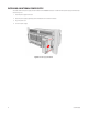
BACK VIEW Thumbscrew for Fastening Modules (12) Fan (10) 10-Pin Power Connector Relay Output Connector AC Power Cord Connector Power Switch Spare Fuse Figure 3.
Installation MOUNTING A CHASSIS The RK5000PS-5U chassis can be mounted into an EIA-standard, 19-inch rack. To mount the chassis into a rack, follow these steps and refer to Figure 4. 1. Insert the chassis into the rack. 2. Secure the chassis to the rack with the supplied screws and washers. Figure 4. Mounting an RK5000PS-5U into a Rack If installing the RK5000PS-5U into a square-hole rack, insert two cage nuts in each side of the square-hole rack as shown in Figure 5. CAGE NUT Figure 5.
INSTALLING A MODULE You can install up to 12 single-width modules into the RK5000PS-5U. To install a module, follow these steps and refer to Figure 6. 1. Insert the module into an empty slot of the chassis. The two slots on the right are for the power supply. 2. Secure the module by tightening the thumbscrew on the back of the chassis. NOTE: Some versions of the Endura module do not have a threaded screw hole for the thumbscrew in the primary threaded standoff to engage.
INSTALLING A BLANK MODULE Single-width blank modules can be used to fill the empty module slots on the chassis. To install a blank module, follow these steps and refer to Figure 7. 1. Insert the blank module into the empty slot on the chassis. 2. Secure the blank module by tightening the thumbscrew on the back of the chassis. Figure 7.
INSTALLING AN INTERNAL POWER SUPPLY The double-width internal power supply must be installed into the RK5000PS-5U chassis. To install the internal power supply, follow these steps and refer to Figure 8. 1. Insert the power supply into the rack. 2. Secure the power supply by tightening the two thumbscrews on the front of the chassis. 3. Plug in the power cord. 4. Turn on the power supply. Figure 8.
Service REPLACING AN INTERNAL POWER SUPPLY You can easily replace the internal power supply in the RK5000PS-5U with a replacement (RK5PWR-300). You will know if there is a problem with the power supply because the blue Pelco badge on the front panel will turn off. Before replacing the power supply, check the fuse. It can be replaced easily with the supplied spare. If the fuse is not the problem, then follow these steps and refer to Figure 8 to replace the power supply. 1. Unplug the AC power cord. 2.
REPLACING A FAN The fan baffle on the RK5000PS-5U has 10 fans. These fans can be replaced easily in case of failure. To replace a fan, follow these steps and refer to Figures 9-12. 1. Unscrew the two thumbscrews on the back of the fan baffle. 2. Lower the back panel until the fans are exposed. 3. Unscrew the two screws that hold the fan in place. 4. Unplug the red 2-pin connector from the bus board. 5. Remove the failed fan and insert the new one. 6. Plug in the 2-pin connector. 7.
Figure 11. Fan Screws Figure 12.
Specifications ELECTRICAL Input Voltage 100-240 VAC, 50-60 Hz, autoranging Output Voltage 12 VDC Power Consumption 300 watts, 154 BTU/H (non-inclusive of components within the rack) Fuse 4 amps/250 V Redundant Capability Yes with optional EPS5000-300 power supply MECHANICAL Number of Slots 12 for modules and 2 for power supply Module Orientation Vertical Rack Units 5 (includes fan baffle) Construction Aluminum Finish Black GENERAL Operating Temperature 14 32˚ to 122˚F (0˚ to 50˚) Oper
PRODUCT WARRANTY AND RETURN INFORMATION WARRANTY Pelco will repair or replace, without charge, any merchandise proved defective in material or workmanship for a period of one year after the date of shipment. Exceptions to this warranty are as noted below: • Five years on FT/FR8000 Series fiber optic products. • Three years on Genex ® Series products (multiplexers, server, and keyboard).
Worldwide Headquarters 3500 Pelco Way Clovis, California 93612 USA USA & Canada Tel: 800/289-9100 Fax: 800/289-9150 International Tel: 1-559/292-1981 Fax: 1-559/348-1120 www.pelco.