Spectra Enhanced Installation Manual INSTALLATION MANUAL C2279M | 2/15
Contents Important Notices . . . . . . . . . . . . . . . . . . . . . . . . . . . . . . . . . . . . . . . . . . . . . . . . . . . . . . . . . . . . . . . . . . . . . . . . . . . . . . . . . . . . . . . . . 3 Regulatory Notices . . . . . . . . . . . . . . . . . . . . . . . . . . . . . . . . . . . . . . . . . . . . . . . . . . . . . . . . . . . . . . . . . . . . . . . . . . . . . . . . . . . . 3 Radio and Television Interference . . . . . . . . . . . . . . . . . . . . . . . . . . . . . . . . . . . . . . . . .
Important Notices Regulatory Notices This device complies with Part 15 of the FCC Rules. Operation is subject to the following two conditions: (1) this device may not cause harmful interference, and (2) this device must accept any interference received, including interference that may cause undesired operation. Radio and Television Interference This equipment has been tested and found to comply with the limits of a Class A digital device, pursuant to Part 15 of the FCC rules.
Open Source Software This product includes certain open source or other software originated from third parties that is subject to the GNU General Public License (GPL), GNU Library/Lesser General Public License (LGPL) and different and/or additional copyright licenses, disclaimers, and notices. The exact terms of GPL, LGPL, and some other licenses are provided to you with this product. Please refer to the exact terms of the GPL and LGPL at http://www.fsf.org (Free Software Foundation) or http://www.
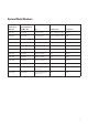
System Model Numbers Spectra Enhanced, 2.0 MPx, 20X Spectra Enhanced, 2.
Parts List Qty 1 1 1 1 1 1 3 Description Back box with mounting hardware Lower dome (includes trim ring and bubble) Dome drive Ferrite (for Class A compliance) Resource disc Installation manual MAC address labels (extra) The following in-ceiling parts are needed but not supplied: Qty 1 1 1 Description Safety chain Conduit fitting and lock nut Cat5e cable or higher Qty 1 1 1 1 1 1 1 3 Description Pendant back box Lower dome (includes trim ring and bubble) Pendant dome drive Ferrite (for Class A complian
Product Overview Figure 1: Connections and Features # Connection/Feature Description 1 24 VAC Power Supplies power to the camera, and operates heater and blower in environmental units. 2 PoE+/HPoE Switch Switch to choose between PoE+ and HPoE. Must be set to the correct position based on what type of PoE injector is used. 3 RJ-45 Network Port Connects the camera to the IP network and supplies power to the camera through the network using Power over Ethernet (PoE+ or HPoE).
Installation Methods You can install the Spectra Enhanced Series dome system using one of the following methods: • Installation in a suspended ceiling or a fixed ceiling. • Installation using a pendant mount (not supplied). Installing the Back Box (In-Ceiling) 1. Locate the center point of the mounting location. 2. Insert the compass tool into the ceiling and draw a circle. 3. Cut out the circle. 4. Attach a conduit fitting (not supplied) and lock nut (not supplied). 5.
AR Figure 3: Alarm/Relay/Audio Connector # Connection/Feature Description 1 24 VAC Power Supplies power to the camera, and operates heater and blower in environmental units. 2 PoE+/HPoE Switch Switch to choose between PoE+ and HPoE. Must be set to the correct position based on the type of PoE injector used. 3 RJ-45 Network Port Connects the camera to the IP network and supplies power to the camera through the network using Power over Ethernet (PoE+ or HPoE).
3. Screw the back box onto the pendant mount and apply thread compound (supplied) to the threads on the back box. NOTE: Thread compound must be applied on both standard and environmental pendants. Not doing so may prevent the units from being separated in the future. 4. Connect the power wiring. Refer to the figure below and the Wiring section for more information.
5. FCC Class A installations: Attach the ferrite (supplied) to the network cable. Attach the ferrite on the cable as close as possible to the camera’s RJ-45 network port. The ferrite must be installed for the camera to meet FCC Class A compliance standards. Failure to correctly install the ferrite can cause harmful interference to radio communications. Figure 7: Installing the Ferrite: Pendant Models Installing the Dome Drive (In-Ceiling) 1.
4. Screw in the three captive fasteners until they are secure. Figure 9: Installing the Dome Drive: Pendant Models Installing the Lower Dome (In-Ceiling/Indoor) 1. Snap the clip on the end of the trim ring leash into the hole on the lip of the back box. 2. Snap the trim ring onto the plastic snap washers on the back box mounting screws. Figure 10: Installing the Lower Dome: In-Ceiling Indoor Models 3. Apply power to the dome.
4. Tighten the screws to secure the lower dome to the back box. 5. Apply power to the dome. The dome system will complete a configuration sequence. Figure 11: Installing the Lower Dome: In-Ceiling Environmental Models Installing the Lower Dome (Indoor/Environmental/Pendant) 1. Attach the back box leash to the lower dome. 2. Align the back box screws with the slots on the lower dome. 3. Push the lower dome onto the back box. 4. Tighten the screws to secure the lower dome to the back box. 5.
Installing the Lower Dome (Stainless Steel/Environmental/Pendant) 1. Attach the back box leash to the lower dome using the nearest retainer screw. Figure 13: Attaching the Leash to the Stainless Steel Lower Dome 14 1 Leash 2 Retainer Screw 2. Lightly apply O-ring lubricant (supplied with the lower dome) to the O-ring, and then install the O-ring in the groove on the trim ring of the lower dome. 3.
4. Push the lower dome into the back box, line upalign the mounting screw holes, and install the two mounting screws. Figure 14: Installing the Stainless Steel Lower Dome 5. Apply power to the dome. The dome system will complete a configuration sequence.
Ethernet Wiring Requirement for POE+ and HPOE A Cat5 cable or higher cable (not supplied) is used to connect the RJ-45 network port during the back box installation process. The 8-pin port includes video through Ethernet, and PoE (PoE+ and HPoE) for the camera. PoE injects power over the same cabling that carries the network data, eliminating the need for a separate power supply. This simplifies the installation and operation of the camera without affecting network performance.
Table B: Ethernet with PoE+ Mode B (Continued) (Sheet 2 of 2) Pin Function 6 RX 7 PoE 3-4 8 PoE 3-4 Table C: High Power PoE Pin Function 1 TX+/PoE– 2 TX–/PoE– 3 RX+/PoE+ 4 PoE+ 5 PoE+ 6 RX–/PoE+ 7 PoE– 8 PoE– 17
24 VAC Wiring Distances Power consumption for the environmental version is 82 VA. Use a 24 VAC transformer with a minimum of 100 VA per dome. Table A: 24 VAC Wiring Distances Wire Gauge AC/DC Total VA 20 AWG (0.5 mm2) 18 AWG (1.0 mm2) 16 AWG (1.5 mm2) 14 AWG (2.5 mm2) 23 VA 38 m (123 ft) 60 m (196 ft) 95 m (311 ft) 151 m (495 ft) 82 VA 11 m (36 ft) 17 m (56 ft) 27 m (89 ft) 43 m (141 ft) NOTE: Wire distances are based on normal condition estimates.
Accessing the Camera By default, users do not have to log in to view video; anyone who accesses the camera can view live video. If you want to prevent users from viewing video without logging in, you must change the permissions for public users. The recommended browsers for your camera are Internet Explorer® or Mozilla® Firefox® for Microsoft® Windows® operating systems and Firefox for Mac® operating systems. 1. Open a web browser. 2. Type the camera’s IP address (192.168.0.
Pelco by Schneider Electric 3500 Pelco Way Clovis, California 93612 USA (800) 289-9100 Tel (800) 289-9150 Fax +1 (559) 292-1981 International Tel +1 (559) 348-1120 International Fax www.pelco.com Pelco, the Pelco logo, and other trademarks associated with Pelco products referred to in this publication are trademarks of Pelco, Inc. or its affiliates. ONVIF and the ONVIF logo are trademarks of ONVIF Inc. All other product names and services are the property of their respective companies.