I N S T A L L A T I O N FT8316/FR8316 Fiber Transmitter and Receiver Sixteen-Channel Digitally Encoded Video C2603M (6/06)
Contents Important Safety Instructions . . . . . . . . . . . . . . . . . . . . . . . . . . . . . . . . . . . . . . . . . . . . . . . . . . . 4 Regulatory Notices . . . . . . . . . . . . . . . . . . . . . . . . . . . . . . . . . . . . . . . . . . . . . . . . . . . . . . . . . . . 6 Product Overview . . . . . . . . . . . . . . . . . . . . . . . . . . . . . . . . . . . . . . . . . . . . . . . . . . . . . . . . . . . . 7 Description . . . . . . . . . . . . . . . . . . . . . . . . . . . . . . . . . . . . . . . .
Important Safety Instructions 1. Read these instructions. 2. Keep these instructions. 3. Heed all warnings. 4. Follow all instructions. 5. Do not use this apparatus near water. 6. Clean only with dry cloth. 7. Do not block any ventilation openings. Install in accordance with the manufacturer’s instructions. 8. Do not install near any heat sources such as radiators, heat registers, stoves, or other apparatus (including amplifiers) that produce heat. 9.
The product and/or manual may bear the following marks: This symbol indicates that dangerous voltage constituting a risk of electric shock is present within this unit. This symbol indicates that there are important operating and maintenance instructions in the literature accompanying this unit. C2603M (6/06) CAUTION: RISK OF ELECTRIC SHOCK. DO NOT OPEN.
Regulatory Notices This device complies with Part 15 of the FCC Rules. Operation is subject to the following two conditions: (1) this device may not cause harmful interference, and (2) this device must accept any interference received, including interference that may cause undesired operation. RADIO AND TELEVISION INTERFERENCE This equipment has been tested and found to comply with the limits of a Class A digital device, pursuant to Part 15 of the FCC Rules.
Product Overview DESCRIPTION The FT8316/FR8316 fiber transmitter and receiver provide the ability to transmit up to 16 composite video channels over one optical fiber (refer to Figure 1). SIXTEEN VIDEO OUTPUTS SIXTEEN VIDEO INPUTS FT8316 TRANSMITTER ONE FIBER FR8316 RECEIVER Figure 1.
MODELS The FT8316/FR8316 fiber transmitter and receiver consist of the following series of models: Multimode Models:* FT8316MSTR Sixteen-channel fiber optic video transmitter; multimode, ST connector FR8316MSTR Sixteen-channel fiber optic video receiver; multimode, ST connector Single-Mode Models:* FT8316SSTR Sixteen-channel fiber optic video transmitter; single-mode, ST connector FR8316SSTR Sixteen-channel fiber optic video receiver; single-mode, ST connector FT8316SFCR Sixteen-channel fiber optic
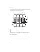
FRONT PANEL The front panel of the FT8316 transmitter and FR8316 receiver provides LED indicators that a llow you to monitor signal status, laser status (transmitter only), and operating power. The following sections provide a view of the front panel of the transmitter and receiver. FRONT PANEL - FT8316 TRANSMITTER Figure 2 illustrates the front panel of the FT8316 transmitter. 16 12 8 4 15 11 7 3 14 10 6 2 13 9 5 1 Figure 2.
FRONT PANEL - FR8316 RECEIVER Figure 3 illustrates the front panel of the FR8316 receiver. 16 12 8 4 15 11 7 3 14 10 6 2 13 9 5 1 Figure 3. Front Panel of FR8316 Receiver VIDEO PRESENT LEDs 1-16 OPTIC FAULT LED, optical signal status indicator, channels 1-8 OPTIC FAULT LED, optical signal status indicator, channels 9-16 NOTE: As indicated above, the two Optic Fault LEDs operate independently of one another.
REAR PANEL Connections to the FT8316 transmitter and FR8316 receiver are made to the rear panel of the modules (refer to Figure 4). 4 8 12 16 3 7 11 15 2 6 10 14 1 5 9 13 Figure 4.
Installation PACKAGE CONTENTS The following items are supplied: 1 FT8316 transmitter or FR8316 receiver 1 Regulated switching power supply with either of the following: • or • 1 Four plug adapters (North American, Australian, U.K., and European); 100-240 VAC, 50-60 Hz input, 12 VDC (25 W) output Three power cords (North American, U.K.
CONNECTIONS Connections to the FT8316 transmitter and FR8316 receiver are made on the rear panel of the modules and consist of the following: • Power connection NOTES: – A 12 VDC or 24 VAC power supply can be used to power the transmitter/receiver when used as a stand-alone module. A 12 VDC power supply is provided. If a 24 VAC power supply is used, the power supply must be a Listed Direct Plug-In Power Unit marked as Class 2 and rated as 24 VAC, 1 A (minimum output).
Troubleshooting LED indicators on the front panel of the FT8316 transmitter and FR8316 receiver (refer to Figure 2 and to Figure 3, respectively) allow you to monitor signal status, laser status (transmitter only), and operating power. Table A provides information about the front-panel indicators and associated troubleshooting guidelines. Table A. Troubleshooting with Front-Panel Indicators Indicator Color Meaning Possible Cause Corrective Action Power LED (Pelco badge) Blue Pelco logo lights.
Table A. Troubleshooting with Front-Panel Indicators (Continued) Indicator Color Meaning Possible Cause Corrective Action Video Present LED (Continued) Red on receiver Incoming video signal is not present on the channel. Optical signal is not being received from the transmitter. Optic Fault LED is also red. Refer to the Optic Fault LED Receiver section in this table. Video source is not powered on. Check power connection to the video source. Video source is not connected to the transmitter.
Table A. Troubleshooting with Front-Panel Indicators (Continued) Indicator Color Meaning Possible Cause Corrective Action Optic Fault LED - Receiver Green The optical signal is being received from the transmitter. Red The optical signal is Transmitter is not powered not being received on. from the transmitter. – Fiber optic cable is not connected. No action required. Check power connections. Replace power supply if necessary. Check fiber optic connections.
Specifications VIDEO Number of Channels Modulation Type Video Input (FT8316)/ Video Output (FR8316) Bandwidth Gain Crosstalk Differential Gain Differential Phase Tilt Signal-to-Noise Ratio GENERAL Operating Temperature Input Power Requirements LED Indicators Dimensions Unit Weight MECHANICAL Connectors Video Rack Power/Alarm Stand-Alone Power Fiber Optic C2603M (6/06) 16 Pulse code modulation, 8-bit resolution 1.0 Vp-p, 75 ohms; NTSC, PAL, and SECAM 6.5 MHz Unity -50 dB typical at 3.58 MHz <1% <1.
OPTICAL POWER BUDGET AND TRANSMISSION DISTANCE Model No. Transmitter Compatible Receiver FT8316MSTR FR8316MSTR Wavelength Optical Power Budget Maximum Transmission Distance 18 dB*† 1 km (0.6 mi)‡ Multimode (62.5/125 µm) 1275 nm 1300 nm Single-Mode (9/125 µm) FT8316SSTR FR8316SSTR 1275 nm 1300 nm 18 dB* 26 km (16.1 mi)§ FT8316SFCR FR8316SFCR 1275 nm 1300 nm 18 dB* 26 km (16.1 mi)§ * Optical power budget is 15 dB when operating temperature range is -40° to 0°C.
PRODUCT WARRANTY AND RETURN INFORMATION WARRANTY Pelco will repair or replace, without charge, any merchandise proved defective in material or workmanship for a period of one year after the date of shipment. Exceptions to this warranty are as noted below: • Five years on FR/FT/FS Series fiber optic products and TW3000 Series unshielded twisted pair transmission products. • Three years on Genex® Series products (multiplexers, server, and keyboard).
Worldwide Headquarters 3500 Pelco Way Clovis, California 93612 USA USA & Canada Tel: 800/289-9100 Fax: 800/289-9150 International Tel: 1-559/292-1981 Fax: 1-559/348-1120 www.pelco.