® BB5A/BB5T Series Back Box Installation/ Operation Manual C1488M-B (2/99) Pelco • 3500 Pelco Way, Clovis • CA 93612-5699 USA • www.pelco.
CONTENTS Section Page 1.0 GENERAL .................................................................................................. 3 1.1 IMPORTANT SAFEGUARDS AND WARNINGS ............................... 3 1.2 REGULATORY NOTICES .................................................................. 4 1.3 UNPACKING INSTRUCTIONS .......................................................... 5 1.4 RECOMMENDED TOOLS ................................................................. 5 2.0 DESCRIPTION ...................
1.0 GENERAL 1.1 IMPORTANT SAFEGUARDS AND WARNINGS Prior to installation and use of this product, the following WARNINGS should be observed. 1. Installation and servicing should only be done by qualified service personnel and conform to all local codes. 2. Unless the unit is specifically marked as a NEMA Type 3, 3R, 3S, 4, 4X, 6, or 6P enclosure, it is designed for indoor use only and it must not be installed where exposed to rain and moisture. 3. Only use replacement parts recommended by Pelco. 4.
1.2 REGULATORY NOTICES NOTE: This equipment has been tested and found to comply with the limits of a Class B digital device, pursuant to part 15 of the FCC rules. These limits are designed to provide reasonable protection against harmful interference in a residential installation. This equipment generates, uses, and can radiate radio frequency energy and, if not installed and used in accordance with the instructions, may cause harmful interference to radio communications.
1.3 UNPACKING INSTRUCTIONS Unpack and inspect all parts carefully. Be sure to save the shipping box and any inserts. They are the safest material in which to make future shipments. If an item appears to have been damaged in shipment, replace it properly in its box and contact the factory at 1-800-289-9100 or 1-559-292-1981 for a replacement. (International customers fax 1-559-348-1120 for authorization and instructions.
2.0 DESCRIPTION The BB5A Series back boxes are used with the SD5 Series of Spectra™ (Software Version 3.0) domes and SD5A Series of Spectra II™ domes. The BB5T Series back boxes are used with the SD5T Series of Spectra™ Lite domes. The BB5A-F and BB5T-F are for indoor installation in hard ceilings or standard 2-foot x 2-foot (61 x 61 cm) suspended ceilings. The BB5A-PB (black), BB5A-PG (light gray), and BB5T-PG (light gray) pendant back boxes are for indoor installation.
3.0 INSTALLATION FOR IN-CEILING MODELS This manual covers the installation of the BB5A-F, BB5A-PB, BB5A-PG, BB5A-PG-E, BB5T-F, BB5T-PG, and BB5T-PG-E back boxes only. For complete installation and operating instructions for the SD5 Series of Spectra™ (Software Version 3.0) domes, refer to manual C1456M-D; for the SD5A Series of Spectra II™ domes and SD5T Series of Spectra™ Lite domes, refer to manual C1487M-B. 3.1 CEILING AND BACK BOX PREPARATION 3.1.
3.1.2 Suspended Ceiling CAUTION: The ceiling tile must be capable of supporting 16 pounds (7.3 kg) of weight. If the ceiling tile will not support this weight, use the optional SD5-P metal panel. CAUTION: Be careful not to cut outside of the line. If you do, you may not be able to install the back box. Also, the trim ring may not cover the hole. 1. Remove the ceiling tile from the ceiling. 2. Locate the center point to drill a hole in the tile. 3.
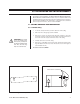
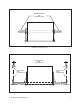
HARD CEILING OR CEILING TILE Figure 4. Installing Back Box HARD CEILING OR CEILING TILE T-RAIL CLIP FOR CEILING TILE T-RAIL CLIP FOR CEILING TILE Figure 5.
CONTROL (RS-422) 7 +5 to +24 VDC EXTERNAL RELAY (WIRING EXAMPLE) Figure 6. Wiring Diagram for Spectra™ (Ver. 3.0) and Spectra II™ THUMBSCREW Figure 7.
Table B. 24 VAC Wiring Distances The following are the recommended maximum distances for 24 VAC with a 10percent voltage drop. (Ten percent is generally the maximum allowable voltage drop for AC-powered devices.
3.3 BACK BOX INSTALLATION OPTIONAL PROCEDURE: If you prefer, you may make the wiring connections inside the back box before installing the back box in the ceiling. To do this, loosen the thumbscrew inside the back box and open the hinged door (refer to Figure 8). Bring the wiring into the back box through the conduit fitting. Follow the steps in Section 3.4, “Back Box Connections,” and then return to this section. CAUTION: The ceiling must be capable of supporting 16 pounds (7.3 kg) of weight.
3.4 BACK BOX CONNECTIONS Depending on the type of dome, refer to either Figure 10 or 11 to attach the wiring to the interconnect circuit board inside the back box. Also refer to Figure 6 or 7 if necessary. WARNING: Make sure you wire power to the outer connectors of the terminal block and ground to the middle connector. Otherwise, you could damage the dome. 1. Earth Ground - Connect earth ground to the middle connector on the power connector. 2.
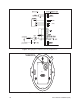
HTR/FAN VIDEO RS-422 CONTROL SIGNALS RX– CONNECTOR FOR OPTIONAL TRANSLATOR SUBASSEMBLY DOME DRIVE CONNECTOR RX+ TX– TX+ PWR IN FUSE POWER (24 VAC ONLY) FAN 24 VAC MIDDLE PIN IS GND 1.6 A Figure 11. Interconnect Circuit Board for Spectra™ Lite 4. Control - If you are using a Coaxitron® controller, control signals will be transmitted over the video coax. If you are using RS-422 (P or D) control signals, connect the control lines from the controller to the circuit board.
4.0 INSTALLATION FOR PENDANT MODELS 4.1 PENDANT-MOUNT INSTALLATION 1. Install the pendant dome mount. Refer to the instructions provided with the mount. If the mount is outdoors, make sure it is properly sealed to keep moisture out. 2. Bring the wiring for the dome through the mount. Refer to Section 3.2, WIRING. 3. Refer to Figure 8. Loosen the thumbscrew inside the back box and open the hinged door. 4. Screw the back box into the mount as far as possible and bring the wiring into the back box.
5.0 TROUBLESHOOTING Symptom: LED does not light. If the red power LED on the door of the interconnect circuit board in the back box does not light: 1. Turn off power. 2. Open the door to the interconnect circuit board and check the fuse. Refer to Figure 10 for the location of the fuse. If the fuse is bad, replace it. To order a replacement fuse from Pelco, specify the part number FUS1.6-5X20FAST. This is a 1.6-ampere fuse, 5 x 20 mm, fast blow. 3.
6.0 SPECIFICATIONS MECHANICAL Construction Back box: Aluminum Cable Entry In-Ceiling: Pendant: .75" (1.91 cm) conduit fitting Through 1.5" (3.81 cm) NPT pendant mount Dimensions: See Figure 12 ELECTRICAL Input Voltage: 18-30 VAC, 24 VAC nominal Input Power In-ceiling: 30 vA Indoor pendant: 30 vA Outdoor pendant: 75 vA Fuse: 1.
Weight In-Ceiling Back Box Pendant Back Box† Unit Shipping 2.6 lbs (1.18 kg) 4.0 lbs (1.81 kg) 2.85 lbs (1.28 kg) 5.0 lbs (2.27 kg) * Assumes no wind chill factor; for detailed test conditions, contact Pelco. † Add 1.25 lbs (.57 kg) for outdoor models with sun shield and heater (Design and product specifications subject to change without notice.) TOP PORTION OF BACK BOX IS REMOVABLE FOR SURFACE MOUNT APPLICATIONS DOME IS SECURED TO CEILING BY MOUNTING BRACKET 7.25 (18.13) 8.52 (21.64) 6.60 (16.
NOTES Pelco Manual C1488M-B (2/99) 19
7.0 WARRANTY AND RETURN INFORMATION WARRANTY Pelco will repair or replace, without charge, any merchandise proved defective in material or workmanship for a period of one year after the date of shipment. Exceptions to this warranty are as noted below: • Five years on FT/FR8000 Series fiber optic products. • Three years on Genex® Series products (multiplexers, server, and keyboard).