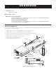
ADDENDUM Addendum No. C1531M Date October 25, 2005 Manuals Affected C1525M-B Manual Update Installation of Support Rails The instructions provided in this section replace the steps listed on page 11 of the Installation/Operation manual for installing the VMX200 in a 19-inch equipment rack. Connecting Analog Video to the VMX200-SYS-Q The instructions provided in this section replace the steps listed on page 15 of the Installation/Operation manual for connecting analog video inputs to the VMX200-SYS-Q.
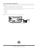
Connecting Analog Video to the VMX200-SYS-Q The video input card that is supplied with the VMX200-SYS-Q has changed, and now it has only four video input connectors. The original configuration described in the VMX200 Installation/Operation manual included the yellow input connector. Now the configuration uses the black input connector instead of the yellow. To connect video inputs to the VMX200-SYS-Q, complete the following steps and refer to Figure 2: 1.
I N S TA L L AT I O N / O P E R AT I O N ® VMX200 Video Management System VMX200-SYS Series C1525M-B (10/02)
2 C1525M-B (10/02)
CONTENTS Section Page IMPORTANT SAFEGUARDS AND WARNINGS .................................................................................................................................................................. 4 DESCRIPTION ..................................................................................................................................................................................................................... 5 MODELS ......................................................
IMPORTANT SAFEGUARDS AND WARNINGS Prior to installation and use of this product, the following WARNINGS should be observed: 1. Installation and servicing should be done only by qualified service personnel and conform to all local codes. 2. Unless the unit is specifically marked as a NEMA Type 3, 3R, 3S, 4, 4X, 6, or 6P enclosure, it is designed for indoor use only and it must not be installed where exposed to rain and moisture. 3.
DESCRIPTION The Pelco VMX200 Video Management System uses a Windows®-based interface for video security system control. You can control matrix switchers, multiplexers, DVRs, VCRs, and Spectra®/Esprit™ camera positioning systems by using mapping configurations and a visual interface. With a mouse, you can click a camera icon within your site map and drag it to a video display window. The VMX200 uses an interactive system schematic to simplify system configuration.
OVERVIEW Figure 1 shows how equipment can be linked together on the VMX200 Video Management System. This illustration is only an example. There are many ways you can link equipment together in this system. NOTE: Each VMX200 workstation has two standard COM ports. Expansion is possible via the USB port. DATA VIDEO MULTIPLEXER DVR MATRIX SWITCHER VCR VMX200-SYS-Q MONITOR WALL Figure 1.
FRONT VIEW Refer to Figure 2 to get familiarized with the front of the VMX200 workstation. The front of the unit has a door that can be opened or locked using one of the supplied keys. Figure 2. VMX200 Front View C1525M-B (10/02) POWER LED RACK EARS HDD (HARD DISK DRIVE) LED FAN KEY LOCK (2 KEYS SUPPLIED) POWER BUTTON FAN VENTILATION CD-RW DRIVE HANDLES 3.
REAR VIEW Figure 3 shows the rear of each VMX200 model. This system does not require the use of all of the ports. VMX200-SYS VMX200-SYS-1 VMX200-SYS-Q Figure 3.
VMX200-SYS MOUSE PORT MONITOR PORT KEYBOARD PORT ETHERNET PORT (NOT USED) USB PORT (NOT USED) S-VHS VIDEO PORT (NOT USED) COM 1 F CONNECTOR PORT (NOT USED) COM 2 PARALLEL PORT*** VIDEO INPUT* VMX200-SYS-1 MOUSE PORT LEFT MONITOR PORT KEYBOARD PORT ETHERNET PORT (NOT USED) USB PORT (NOT USED) DB15 PORT (NOT USED) COM 1 S-VHS VIDEO PORT (NOT USED) COM 2 F CONNECTOR PORT (NOT USED) VIDEO INPUT* PARALLEL PORT***
INSTALLATION The following items are supplied: • • • • • • • • • • • • 1 1 1 1 1 2 2 2 2 1 1 1 VMX200 workstation Mouse Keyboard Video input adapter Y adapter (VMX200-SYS-Q) or 1 plug adapter (VMX200-SYS-1) Power cords (1 USA standard and 1 European standard) Adjustable support rails with screws and nuts Rack-mount ears with screws Keys Video input card software package VMX200 system software package Windows 2000 startup package One VGA or SVGA monitor is required for the VMX200-SYS and two VGA or SVGA m
MOUNTING The VMX200 can be placed on a flat surface, such as a shelf or table, or it can be mounted in a 19-inch (48.26 cm) equipment rack. Follow these instructions to mount the workstation in an equipment rack: 1. Attach the two adjustable support rails to the sides of the equipment rack using the eight 10-32 x .375-inch screws. Also use the eight 10-32 nuts if the rack does not have threaded mounting holes. 2. Tighten the eight 10-32 x .250 screws. 3.
CONNECTIONS MOUSE AND KEYBOARD Connect the mouse and keyboard to the workstation. Figure 5 shows the VMX200-SYS model, but the connections are the same for the other two models. VMX200-SYS Figure 5.
MONITOR OUTPUTS If you have the VMX200-SYS model, you have to connect only one monitor. The VMX200-SYS-1 and VMX200-SYS-Q each require two monitors. Refer to Figure 6. The VMX200-SYS-Q uses an overlay. This allows a quad display. The location of the monitors is important. The graphical map monitor must always be placed on the left and the video display monitor must always be placed on the right.
VIDEO INPUTS The VMX200-SYS and VMX200-SYS-1 have one video input. The VMX200-SYS-Q has six video inputs. Follow these steps and refer to Figure 7 to connect the video: 1. 2. Connect a spider cable to the video port on each model. Connect the video input to the video source (for example, cameras or monitor output of a switch or multiplexer). NOTE: Refer to the Installation/Operation Manual for each device you connect for further video connection information.
VMX200-SYS S-VIDEO IN (BLACK) AUDIO IN RIGHT (RED) AUDIO IN LEFT (WHITE) VIDEO IN (YELLOW) SPIDER CABLE * * REQUIRES RCA-TO-BNC ADAPTER VMX200-SYS-1 S-VIDEO IN (BLACK) AUDIO IN RIGHT (RED) AUDIO IN LEFT (WHITE) VIDEO IN (YELLOW) SPIDER CABLE * * REQUIRES RCA-TO-BNC ADAPTER VMX200-SYS-Q SPIDER CABLE INPUT 1 2 3 4 5 6 COLOR RED GREEN BLUE YELLOW BLACK WHITE Figure 7.
DATA CONTROL The following sections provide instructions and illustrations on how to connect numerous devices to the VMX200 for data control. Each application shows a VMX200-SYS for illustration purposes only. You can also use a VMX200-SYS-1 or VMX200-SYS-Q. NOTE: You can use either COM 1 or COM 2 on the VMX200 for control.
CM6800 CONTROL CONNECTIONS There are two ways you can connect a CM6800 to a VMX200. Connect a null modem cable from VMX200 COM 1 or COM 2 to the CM6800 COM 1 port. Connect a DB9 cable from VMX200 COM 1 or COM 2 to the CM6800 ASCII Ports 2, 7, or 8. You must use a wall block to convert the DB9 connector to an RJ-45 connector. Figure 9. CM6800 Control Connections Although a CM6800-48X8 is pictured above, you can use a CM6800-32X6 as long as the COM port number of the port connection is the same.
CM6700 CONTROL CONNECTIONS Follow these steps and refer to Figure 10: 1. Connect a DB9 cable from VMX200 COM 1 or COM 2 to the screw terminal connector on the CM6700. Note the pin-outs on the wiring. 2. Remove the cover from the CM6700-MXB and set the SW5 DIP switch to RS-232 mode. Replace the cover when done. After you make the connections, open the Device Configuration window in the VMX200 software and add the CM6700 to your system.
CM9760/9740 CONTROL CONNECTIONS There are two ways you can make the connections: 1. 2. Via SERCOM Ports Via Data Translator SERCOM Ports This is called the Virtual Keyboard Method because the SERCOM ports used for the VMX200 must be programmed as keyboard ports. Pelco recommends this method because it supports all system control functions. Follow these steps and refer to Figure 11. 1. Connect a PV130 converter to VMX200 COM 1 or COM 2. 2.
Data Translator You can also connect the CPU to a VMX200 via the CM9760-DT. This method does not allow complete control of cameras connected serially to the CM9760/9740-CC1 (including presets). Therefore, Pelco recommends this method only for situations where the Virtual Keyboard Method is not possible. Follow these steps and refer to Figure 12: 1. Connect a null modem cable from VMX200 COM 1 or COM 2 to CM9760-DT COM A. 2.
CM8500 CONTROL CONNECTIONS 1. Connect a null modem cable from VMX200 COM 1 or COM 2 to the DB9 connector on the CM8500-DT. 2. Connect an RJ-45 straight cable from the RJ-45 connector on the CM8500-DT to one of the RJ-45 connectors on the CM8500. After you make the connections, open the Device Configuration window in the VMX200 software and add the CM8500 to your system. Refer to the VMX200 Software Installation/Operation Manual for detailed instructions on system configuration.
GENEX MULTIPLEXER CONTROL CONNECTIONS Follow these steps and refer to Figure 14: 1. Connect a DB9 cable from VMX200 COM 1 or COM 2 to a wall block. Note the pin-outs. Pins 1 and 8 are tied together with Pin 5. 2. Connect an RJ-45 straight cable from the wall block to the Genex® COM OUT port. After you make the connections, open the Device Configuration window in the VMX200 software and add the Genex Multiplexer to your system.
TLR3000 SERIES VCR CONTROL CONNECTIONS Connect a null modem cable from VMX200 COM 1 or COM 2 to the TLR3168/TLR3096 RS-232 serial port. Refer to Figure 16. NOTE: Pelco recommends that the null modem cable be checked with an ohmmeter to ensure that the pin connections match those listed in the figure below. After you make the connections, open the Device Configuration window in the VMX200 software and add the VCR to your system.
CM9760-ALM CONTROL CONNECTIONS Follow these steps and refer to Figure 16: 1. 2. 3. Connect a PV130 converter to VMX200 COM 1 or COM 2. Wire a cable from the PV130 to a wall block. Connect an RJ-45 reversed cable from the wall block to the COM IN connector on the CM9760-ALM. After you make the connections, open the Device Configuration window in the VMX200 software and add the CM9760-ALM to your system.
CM9760-REL CONTROL CONNECTIONS Follow these steps and refer to Figure 17: 1. 2. 3. Connect a PV130 converter to VMX200 COM 1 or COM 2. Wire a cable from the PV130 to a wall block. Connect an RJ-45 reversed cable from the wall block to the COM IN connector on the CM9760-REL. After you make the connections, open the Device Configuration window in the VMX200 software and add the CM9760-REL to your system.
OPERATION Refer to the VMX200 Software Installation/Operation Manual for instructions on how to operate the Video Management System.
REGULATORY NOTICES This equipment has been tested and found to comply with the limits of a Class B digital device, pursuant to part 15 of the FCC rules. These limits are designed to provide reasonable protection against harmful interference in a residential installation. This equipment generates, uses, and can radiate radio frequency energy and, if not installed and used in accordance with the instructions, may cause harmful interference to radio communications.
® World Headquarters 3500 Pelco Way Clovis, California 93612 USA USA & Canada Tel: 800/289-9100 Fax: 800/289-9150 International Tel: 1-559/292-1981 Fax: 1-559/348-1120 www.pelco.