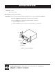
ADDENDUM Addendum No. C1573M Date February 1, 2006 Manuals Affected C1572M, C1555M-F, C1566M-C Manual Update The front and rear mounting rails and the mounting brackets are no longer supplied with the CM9700-CC1. Disregard the CM9700-CC1 mounting information in the above referenced manuals. To mount the CM9700-CC1 into a standard 19-inch EIA rack follow these instructions: 1. Insert the CM9700-CC1 into the rack. 2. Tighten the CM9700-CC1 to the rack using the four supplied Phillips screws with washers.
INSTALLATION/OPERATION System 9770 ® C1555M-F (10/05)
Contents Contents. . . . . . . . . . . . . . . . . . . . . . . . . . . . . . . . . . . . . . . . . . . . . . . . . . . . . . . . . . . . . . . . . . . . . . . . . . . . . . . . . . . . . . . . . . . . . . . . . . . . . . . . . . . . .3 List of Illustrations . . . . . . . . . . . . . . . . . . . . . . . . . . . . . . . . . . . . . . . . . . . . . . . . . . . . . . . . . . . . . . . . . . . . . . . . . . . . . . . . . . . . . . . . . . . . . . . . . . . . .4 Description . . . . . . . . . . . . . . . . . . . .
List of Illustrations 1 2 3 4 5 6 7 8 9 10 11 12 13 14 15 16 17 18 19 20 21 22 23 24 25 26 27 28 29 30 31 32 33 34 35 36 37 38 39 40 41 42 43 44 45 46 4 CM9770-MXB Mounting Baffle . . . . . . . . . . . . . . . . . . . . . . . . . . . . . . . . . . . . . . . . . . . . . . . . . . . . . . . . . . . . . . . . . . . . . . . . . . . . . . . . . . .10 Mounting the CM9770-MXB on Top of the Mounting Baffle . . . . . . . . . . . . . . . . . . . . . . . . . . . . . . . . . . . . . . . . . . . . . . . . . . . . . .
List of Tables A B C D E F G H I J K L M N LEDs Illuminated During a Basic Check . . . . . . . . . . . . . . . . . . . . . . . . . . . . . . . . . . . . . . . . . . . . . . . . . . . . . . . . . . . . . . . . . . . . . . . . . . . . . . .16 Data Connections—Single Node Systems Without a Hot Switch . . . . . . . . . . . . . . . . . . . . . . . . . . . . . . . . . . . . . . . . . . . . . . . . . . . . . . . . . .31 Data Connections—Networked System Without a Hot Switch . . . . . . . . . . . . . . . . . . . .
Description The System 9770 is a full-featured video matrix switching control system that allows users to view and control up to 2,048 cameras and 512 monitors on a single node. The System 9770 has the following basic components: • CM9700-CC1—This is the system CPU; connect matrix bays, keyboards, PTZ camera control lines, and peripheral devices to the CC1.
MODELS Controller and CPU Components CM9700-CC1 CPU controller; 120 VAC, 60 Hz or 230 VAC, 50 Hz. CM9700-SER Serial communication card (RS-422 SERCOM); provides 8 communications ports to interface peripheral equipment (4 maximum per CPU). CM9700-SER-32 Port expansion unit; 32 serial communication (SERCOM) ports per unit. Up to three units can be added to a CC1. (Check with Pelco Systems Applications Department before adding to an existing CM9700-CC1).
Keyboards The following keyboards are compatible with the System 9770: CM9760-KBD Full-function desktop variable-speed keyboard; 120 VAC, 60 Hz. CM9760-KBD-X Same as CM9760-KBD except 230 VAC, 50 Hz. CM9760-KBR Full-function 19-inch EIA rack mount keyboard; 120 VAC, 60 Hz. CM9760-KBR-X Same as CM9760-KBR except 230 VAC, 50 Hz. NOTE: CM9760-KBD software version 8.03 or higher is required.
Installation UNPACKING 1. Unpack and inspect all equipment, and verify delivery according to the packing slip. Before shipping, Pelco connects, tests, and programs each system according to the individual sales order. Contact Pelco immediately if there is any discrepancy in the equipment that you receive.
MOUNTING Install the System 9770 in EIA-standard 19-inch (48.26 cm) racks. CM9770-MXB 1. Install the CM9770-MXB mounting baffle first (refer to Figure 1). The mounting baffle uses 1 rack unit (RU), and it has front and rear mounting ears, which are attached to the front and rear mounting racks. The rear mounting brackets are adjustable to allow for different depths of cabinets. NOTE: Be sure to use all eight screws provided with the mounting baffle.
Figure 2. Mounting the CM9770-MXB on Top of the Mounting Baffle (Optional) Install additional CM9770-MXB mounting trays and matrix bays to the side of and below the first unit, as necessary. WARNING: Always install equipment starting from the bottom of the rack frame or cabinet. Installing equipment from the top down will make a rack or cabinet top heavy and could cause the equipment to tip over. NOTE: Each CM9770-MXB has a unique label for identifying the bay location in the installation.
c. Attach the ear of the rear-mounting support rail to the rear of the equipment rack using four 10-32 x 0.375-inch flat head screws. (The holes in the ear of the rail should align with the threaded holes in the equipment rack.) 4. Tighten the three 8-32 x 0.375-inch pan head screws and washers that were attached to the front- and rear-mounting support rails in step 2 above. 5. Repeat steps 3 and 4 for the second set of support rails. 6.
VIDEO INPUT/OUTPUT CONNECTIONS The following steps provide an overview of how to connect video input and output sources. More complete procedures are provided in the subsequent sections. NOTE: If your System 9770 is configured by Pelco, the appropriate number of video input cards and monitor output cards and BNC rear panels are installed at the factory, and steps 1 and 2 are not necessary. If this is the case, skip to Step 3. 1. Install the CM9770-VCC and CM9770-VMC cards in the matrix bay.
INSTALLING VIDEO INPUT CARDS (CM9770-VCC) The first video input card is inserted into slot 1; the next card is inserted into slot 2 (refer to Figure 4). To add a video card, slide the card into the first available slot. The CM9770-MXB can contain a maximum of eight viideo input cards. HOT SWAPPING: You can “hot swap” a video input card—remove a card and/or insert a new card—while the system is powered and running.
INSTALLING MONITOR OUTPUT CARDS (CM9770-VMC) The monitor output card located in slot 10 is the primary card, and it handles video for monitors 1-16. Refer to Figure 5. Note that the CM9770-MXB will not function without a CM9770-VMC card inserted into slot 10. An optional secondary VMC card can be installed in slot 9. This card routes video for monitors 17-32. HOT SWAPPING: You can “hot swap” a monitor output card—remove a card and/or insert a new card— while the system is powered and running.
PERFORMING A BASIC LED CHECK You should perform a basic LED check before you connect any video input or output to the matrix bay. The LED check allows you to ensure that the system is operating properly. 1. Turn on the power switch on the rear of the matrix bay. The front cover can either be open or closed during the LED check. 2. Various LEDs will blink during the initialization process as the software verifies communication and version level information.
INSTALLING REAR PANEL BNC CARDS The following rear panel cards can be used with the CM9770-MXB matrix bay: • CM9770-RPC—the BNC card for video connections • CM9770-RPM—the BNC card for monitor connections • CM9770-DFC—this is a downframe card and cable assembly used to connect multiple matrix bays; refer to the Downframing section in the Appendix for more information • CM9770-DFL—this downframe card and cable assembly is the same as the CM9770-DFC, except that it also has BNC connectors for looping i
Change the Termination Jumpers on a Rear Panel Video BNC Card In a single-bay, non-looping configuration (up to 256 cameras and 32 monitors), the jumpers must be set in the terminated position. Refer to the Installing Additional Matrix Bays—Sideframing and Downframing section in the Appendix for details on termination jumper settings in multiplebay configurations.
Looping Video When looping video out to another device (such as a DVR, VCR, or switcher), the connection instructions depend on the size of your system, as follows: • In a system containing 32 monitors or fewer (the video is not downframed), use the CM9700-VPP panels to loop the video out. Connect the DFC cables that are provided with the VPP panel to the connectors on the bottom of the matrix bay RPC cards, as shown in Figure 10.
Insert or Replace a Rear Panel Monitor BNC Card (CM9770-RPM) 1. Slide the monitor BNC card into the card guides at the rear of the bay. From the rear of the bay, the slot at the far left provides the connection point for the primary monitor output card inserted in the front of the bay into slot 10. NOTE: Each monitor BNC card (CM9770-RPM) provides 16 monitor output connections and connects to one monitor output card (CM9770-VMC).
VIDEO INPUT/OUTPUT CAPACITY Single Bay A single CM9770-MXB can support up to 256 camera inputs (in increments of 32) and 32 monitor outputs (in increments of 16). Refer to Figure 12. CM9700-CC1 CAM 17 CM9770 MXB .................. CAM 1 MONITOR 1 MONITOR 32 CAM 256 Figure 12.
Multiple Bays, Single Node In a single-node system with one CM9700-CC1 (not networked), you can connect multiple CM9770-MXBs using “sideframing” and “downframing” for a maximum capacity of 2,048 camera inputs and 256 monitor outputs. NOTE: When using CM9760-MDA units, you can increase the monitor output capacity to a maximum of 512. Refer to the Downframing section in the Appendix for more information on using CM9760-MDA units.
CM9700-CC1 SIDEFRAME CABLES MONITOR 32 MONITOR 1 TO CM9700-CC1 TO CM9700-CC1 OUTPUT BAY TO CM9700-CC1 CAMERA 257 CAMERA 1 OPTIONAL: ADD CM9770-VCC INPUT CARDS AND BNC INPUT CARDS AS NECESSARY TO CONNECT SIDEFRAME CABLES FROM ADDITIONAL BAYS OR TO CONNECT CAMERAS DIRECTLY TO THE OUTPUT BAY (WHEN USING SEVEN MATRIX BAYS OR FEWER) ROUTE SIDEFRAME CABLES FROM ADDITIONAL BAYS TO NEXT AVAILABLE BNC INPUT CARDS ON OUTPUT BAY.
• Downframing—To expand the matrix video outputs beyond 32, you can loop the video from the first CM9770-MXB to subsequent CM9770-MXB units for an additional 32 monitor outputs on each matrix bay. Refer to Figure Figure 15.. You can connect a maximum of eight bays in a downframing configuration for a total MXB capacity of 256 monitors; in addition, you can increase monitor capacity further by using MDA units, for a total single-node system capacity of 512 monitors.
Networked System A networked system with multiple nodes uses an NIU (network interface unit) to combine up to 24 CM9700-CC1 systems into a network—each CC1 system is called a “node.” Multiple CM9770-MXB units can be connected to each CC1 through sideframing and downframing. An NIU is a CM9700-CC1 loaded with networking software, sold as a CM9700-NW1. Refer to Figure 16.
THE POWER SUPPLY MODULE (CM9700-MPS) You can add a backup power supply module (CM9700-MPS) to a System 9770 matrix bay to provide redundancy to the bay’s power supply. NOTE: You can “hot swap” a backup power supply module—remove and/or insert a backup power supply—while the system is powered and running. INSTALL A BACKUP POWER SUPPLY 1. Open the matrix bay front cover. 2. Remove the blank-off plate from the empty power input slot. 3. Slide the power input module partially into the bay, on the guide rail.
HOW TO REPLACE THE FUSE IN A POWER SUPPLY MODULE The matrix bay is shipped from the factory configured for the correct input power. The power input panel, on the rear panel of the matrix bay, provides two separate power input receptacles, one for each power supply. NOTE: The power input panel is not serviceable and should be removed or installed only by Pelco. Each power input receptacle is equipped with a fuse assembly. In addition, each fuse assembly also provides a spare fuse. Refer to Figure 18.
HOW TO TURN OFF THE AUDIBLE POWER SUPPLY ALARM The power supply module contains an audible alarm, which operates in conjunction with the fault LEDs located on the power supply front panel. To turn off this alarm, complete the following steps: 1. Turn off the matrix bay power. 2. Remove the power supply module from the matrix bay frame. 3. Move the speaker switch to the OFF position (refer to Figure 19). 4. Insert the power supply module back into the matrix bay frame. 5. Turn on the power.
SYSTEM DEVICE CONNECTIONS 1. Turn off power to all system devices and disconnect all power line cords while connecting system devices. 2. Complete the following steps to connect one or more CM9760-KBD system keyboards. NOTE: CM9760-KBD software version 8.03 or higher is required. a. Connect the keyboard to the CM9505-UPS using the straight cable supplied with the keyboard. b. Connect the CM9505-UPS to one of the RS-422 COM ports on the CC1 using the 6-foot (1.
CM9700-MGR PC COM PORT RS-232 CABLE CM9700-CC1 COM 1/COM 2 PIN 3 (TX) PIN 2 (RX) PIN 2 (RX) PIN 3 (TX) PIN 5 (GND) PIN 5 (GND) DB9 FEMALE DB9 FEMALE Figure 22. CM9700-MGR PC Pin-Out Detail 6. Install any additional system peripheral devices. Refer to the manuals for the individual devices for instructions. Refer to the Data Connections section and your Port Assignments table for directions on which port to use for each device. 7. Connect all power line cords to the equipment.
RS-422 COM PORT (“SERCOM”) CONNECTIONS All peripheral equipment in a System 9770 connect through the RS-422 COM ports on the CM9700-CC1 rear panel. (These ports are also known as “sercom” ports, short for “serial communication” ports.) If you exceed the number of CM9700-CC1 rear panel ports available, you can add ports with the CM9700/9760-SER port expander unit.
Table D. Data Connections—Single Node, Hot-Switched System MXB connection(s) CC1 port 6 and next consecutive ports, as necessary—connected through the hot switch. Hot Switch connection CC1 port 5. Other peripherals Any available port(s)— connected through the hot switch. These connections do not have to be in sequential ports. Table E. Data Connections—Networked, Hot-Switched System MXB connection(s) CC1 port 7 and next consecutive ports, as necessary—connected through the hot switch.
CM9700-CC1 REVERSED CABLE PIN 1 CM9770-MXB PIN 8 CM9770-MXB RJ-45 PIN-OUTS REVERSED DATA CABLE PIN 1 = TX+ PIN 2 = TXPIN 7 = RXPIN 8 = RX+ CM9700-CC1 RJ-45 PIN-OUTS PIN 1 = TX+ PIN 2 = TXPIN 7 = RXPIN 8 = RX+ Figure 23. Sample CM9770-MXB to CM9700-CC1 Connection CM9700-NW1 CM9700-CC1 NODE 5 CM9700-CC1 NODE 7 CM9700-CC1 NODE 6 CM9770-MXB CM9770-MXB CM9770-MXB Figure 24.
System Start-Up To start up your system you must complete the following tasks: 1. Install the CM9700-MGR on a PC connected to the CC1. Refer to System Device Connections in the Installation section for instructions on connecting a PC to the CC1. Refer to the CM9700-MGR Software Guide for instructions on installing the CM9700-MGR software. 2. Complete the following steps on the CM9700-MGR PC (instructions are provided in the CM9700-MGR Software Guide): a. Copy the CM9700 system design file (the *.
VERIFY SYSTEM OPERATION 1. Power up all the remaining equipment. 2. After the CM9700-CC1 loads the configuration files, “SYSTEM 97XX” appears on the CM9760-KBD LCD. 3. Enter the default operator password on the CM9760-KBD keypad. “ENTER MONITOR #” appears on the LCD. NOTE: The default password for operator 1 is 0101; operator 2 is 0202; operator 3 is 0303; and so on. These numbers are defined in the Operator PIN field in CM9700-MGR. 4. Enter 1, and then press the MON key.
DISPLAY THE CM9770-MXB SOFTWARE VERSION LEVEL To display the software version level on a system monitor, complete the following steps: 1. Enter the monitor number, and then press the MON key. 2. Enter 999997, and then press the CAM key. The software version number appears on the monitor. DISPLAY A BLUE RASTER SCREEN To display a blue raster screen on a system monitor, complete the following steps: 1. Enter the monitor number, and then press the MON key. 2. Enter 999999, and then press the CAM key.
Programming Your System When you open CM9700-MGR, the Getting Started dialog box appears.. Figure 27. Getting Started Dialog Box The CM9700-MGR provides the following configuration options: • Setup Wizard: This option opens the Setup Wizard (a series of dialog boxes), which provides assistance in setting up a new system. • New System: This option opens the CM9700-MGR main window with a blank system. Use this option when you want to create a new system configuration from scratch.
GETTING HELP USING CM9700-MGR Instructions for how to use CM9700-MGR are provided throughout the software. The CM9700-MGR provides wizards to help users complete tasks, such as adding a device or a group. Each wizard screen contains instructions and explanatory text. Figure 28. Sample Wizard Page When you are working within the grid view or tree view on the CM9700-MGR main window, help is provided as “real-time” help.
Operation A brief description of System 9770 operation is provided here. Power-up the system. Refer to the System Start-Up section. Switch monitor. Enter the monitor number. Press the MON key. Select camera. Enter the camera number. Press the CAM key. Control PTZ receivers. Use the appropriate PTZ control keys or joystick (depending on the keyboard used). Call a preset. Program the preset through the keyboard. Enter the preset number.
Appendix SYSTEM ARCHITECTURE The System 9770 is similar to Pelco’s System 9760 but uses different matrix bay hardware and provides more features. Users familiar with the System 9760 should note the following differences: • Each System 9770 video input card (CM9770-VCC) receives input from 32 video connections (from the CM9770-RPC BNC input card, which contains 32 BNC connectors). A fully loaded CM9770-MXB matrix bay supports 256 video inputs with just eight video input cards.
INSTALLING ADDITIONAL MATRIX BAYS—SIDEFRAMING AND DOWNFRAMING When either more cameras and/or more monitors are needed than can be accommodated by one matrix bay (256 x 32), you can install additional matrix bays in either of the following configurations: • Sideframing—This option increases the number of available video inputs. • Downframing—This option increases the number of monitors available for output.
Downframing To expand the matrix video outputs beyond 32, you can downframe the video from the first CM9770-MXB to subsequent CM9770-MXB units for an additional 32 monitor outputs on each matrix bay. Refer to Figure 31. You can connect a maximum of eight bays in a downframing configuration for a total MXB capacity of 256 monitors; in addition, you can increase monitor capacity further by using MDA units, for a total single-node system capacity of 512 monitors.
Refer to the Downframing section on the following page for instructions on setting the termination jumpers in the downframed bays. Figure 31. Downframing with DFC Cards C1555M-F (10/05) Figure 32.
A downframe cable is used to connect the bottom connector of the RPC card to a downframe card. Figure 33. DFC Cable Downframe Cards The following downframe cards are available for the System 9770: • CM9770-DFC—This is the “no looping” downframe card. • CM9770-DFL—This is the “looping” downframe card. If you are downframing to only one bay, the downframed bay can be populated with either DFL or DFC cards.
TERMINATED UNTERMINATED INPUT FROM BAY ABOVE (LOWER-NUMBERED SLOT) JP16 JP15 JP14 JP13 JP12 JP11 32 1 JP10 JP9 JP8 JP7 JP6 JP5 JP4 JP3 JP2 JP1 OUTPUT TO BAY BELOW (LOWER-NUMBERED SLOT) UNTERMINATED TERMINATED INPUT FROM BAY ABOVE (HIGHER-NUMBERED SLOT) JP32 JP31 JP30 JP29 JP28 JP27 JP26 JP25 JP24 JP23 JP22 JP21 JP20 JP19 JP18 JP17 OUTPUT TO BAY BELOW (HIGHER-NUMBERED SLOT) Figure 34. DFC Card Figure 35.
HOW TO INSTALL OR REPLACE A CM9700-SER CARD IN THE CC1 If you have ordered a replacement or additional CM9700-SER serial communication card, complete the following steps to configure the jumpers on the CC1 board for the slot position the new SER card will occupy. NOTE: When connecting peripheral equipment to the serial communication ports, shielded cabling is required to comply with CE emissions guidelines. 1. Turn off the CC1 power switch.
W1 IRQ SELECT IRQ 15 IRQ 14 IRQ 12 IRQ 10 IRQ 11 IRQ 7 IRQ 9 IRQ 5 IRQ 6 PIN 21 IRQ 4 PIN 22 PIN 1 IRQ 3 PIN 2 W2 ADDRESS SELECT PIN 2 PIN 4 PIN 1 PIN 3 Figure 37. SER Card Jumper Assignments 4. Insert the new SER card into an available ISA slot. The default CM9700-CC1 configuration provides SER cards in ISA slots 1 and 2, so you will most likely insert the new card into slot 3 or 4. Refer to Figure 38. 5. Replace the top cover of the CC1. 6. Power up the CC1.
VIDEO INPUT CARD (CM9770-VCC) DETAIL VSYNC OFF ON GREEN AMBER RED AMBER Figure 39. CM9770-VCC Card Table H. Video Input Card (CM9770-VCC) LEDs 48 Front Panel Label Color When LED Is On + Green The +5 VDC power source is functioning properly. - Green The -5 VDC power source is functioning properly. HB Amber The CPU is active; this “heartbeat” LED blinks at a different rate, according to the current activity: 0.
MONITOR OUTPUT CARD (CM9770-VMC) DETAIL DIP SWITCH GREEN AMBER Figure 40. CM9770-VMC Card Table I. Monitor Output Card (CM9770-VMC) LEDs Front Panel Label Color When LED is on or blinking + Green The +5 VDC power source is functioning properly. - Green The -5 VDC power source is functioning properly. HB Amber The CPU is active; this “heartbeat” LED blinks at a different rate, according to the current activity: Primary VMC—0.
The monitor output card DIP switch selects various options. These switches are set in the proper position at the factory, but they can be changed, if necessary. Table J.
NETWORKING Networking of systems is required when the following conditions apply: • Two or more individual systems need to share video and control features. The CM9700-NW1 network interface unit (NIU) allows you to link any combination of the following systems into a network: – One or more System 9740 or 9760 systems (note that the CM9740-CC1/CM9760-CC1 must be upgraded to software version level 9.01) – One or more System 9770 or 9780 systems • More than 2,048 cameras are required.
CONNECTING SATELLITE DEVICES You can connect a CM6800E-48X8 matrix switcher or a CM9760-SAT device to the System 9770. Refer to the CM9760-SAT Installation/Operation manual or to the CM6800E-48X8 Installation/Operation manual for instructions. The procedure for using a satellite device with a CM9700-CC1 is the same as for a CM9760-CC1, except that the programming within CM9700-MGR is more user-friendly. You just need to add the satellite device using the Add Device wizard.
HOW TO INSTALL VIDEO PATCH PANELS (CM9700-VPP) There are two ways you can mount a CM9700-VPP video patch panel into a rack. 1. Single panels onto a rack 2. Up to 16 panels using the CM9700-VPP-RK The following illustration shows how to mount a single panel onto a rack. The panel is mounted horizontally. RACK CABLE BRACKET CM9700-VPP (4) SCREWS, 10-32X3, PHILLIPS PANHEAD WITH WASHERS RACK MOUNT BRACKET Figure 44.
MOUNTING THE CM9770-MXB IN AN OPEN RACK Figure 46.
DOS ENVIRONMENT AND COMMAND REFERENCE DOS stands for Disk Operating System. Every time you turn on the CM9700-CC1 or every time you reboot (Alt +Ctrl +Del), the computer loads DOS from the CC1 disk into the memory (RAM). Once loaded DOS lets you run other programs, in particular, the CM9700.EXE program. On factory-configured systems the autoexec.bat file is configured for one of the following scenarios: • The boot process ends at the following system prompt (c:\9700>).
File Names and DOS File names in DOS are limited to eight characters. If you issue a command to change the name of the configuration files in the 9700 directory to a name exceeding eight characters, the name is truncated to eight characters. The Windows-based CM9700-MGR program does not allow you to use more than eight alphanumeric characters when creating a name for your set of configuration files. DOS Commands DOS commands are divided into two groups.
If you entered the same command again (CD..) at the c:\9700> prompt and pressed the ENTER key, you would finally end up again at the root directory as previously done. To proceed directly from the directory you are in to another directory, no matter where in the directory tree you are, enter the total directory path of the location you wish to go to at the system prompt. For example, to get to the C:\9700\BKUPTST directory from the root directory, type C:\> CD [directory path], and then press the ENTER key.
DOS REFERENCE The following table provides a list of the most common DOS commands that you are most likely to use when operating the CC1. In addition, you can use the command HELP to access the MS-DOS command reference on the CC1. NOTE: In DOS, the backslash symbol (“ \ “) used alone, refers to the root directory. The [..] symbol refers to the parent directory. Table K.
COMMAND EXAMPLE(S) FASTHELP C:\>FASTHELP Lists and briefly describes every command provided with MS-DOS. This list is much less detailed than the list you get using the “HELP” command. C:\>FASTHELP DIR Specifies the name of the command that you wish FASTHELP to give information about. In this example, DIR. C:\>FORMAT A: Formats a disk for use with MS-DOS. FORMAT C:\>FORMAT A:/S HELP SWITCHES /S COMMENTS Transfers system files to the formatted disk.
Troubleshooting Problems with the CC1 Problems with the CC1 as part of a 9770 system may occur in the following areas: • The CC1 itself • Setup files (also known as configuration files) • Peripheral devices connected to the CC1 • DOS operating system A log is recommended for keeping track of changes made to the system. The log should document the change made, why it was made, the date it was made, and the person responsible for the change.
Monitor Display Problems Problem: Text characters (such as in camera titles) do not display properly. Solution: The CM9770-VMC monitor output card in the matrix bay may not be set for the correct video format (NTSC or PAL). Check switch 1 on the DIP switch and verify that the switch is in the correct position, as identified in Table N. Refer to Figure 40 for an illustration of the DIP switch. Table N.
Specifications CM9700-CC1 ELECTRICAL Input Voltage 120 VAC, 60 Hz or 230 VAC, 50 Hz, autoranging Power Consumption 57 watts Processor Pentium® class CPU Clock Speed 733 MHz Memory 64 MB RAM Disk Drive 3.5-inch, 1.
CM9770-MXB ELECTRICAL Input Voltage 100-240 VAC, 50/60 Hz, autoranging Power Consumption 60 watts maximum (fully populated) Communication Full duplex RS-422 using an RJ-45 connector VIDEO Inputs Card slots support up to 256 inputs per bay Outputs Two output card slots for supporting 32 outputs per bay Video Input Level 0.5 to 2 Vp-p, RS-170 composite video Impedance 75 ohms terminating (looping versions available) Crosstalk–Adjacent Channel -61 dB at 3.
Regulatory Notices CM9780-MXB This device complies with Part 15 of the FCC Rules. Operation is subject to the following two conditions: (1) this device may not cause harmful interference, and (2) this device must accept any interference received, including interference that may cause undesired operation. RADIO AND TELEVISION INTERFERENCE This equipment has been tested and found to comply with the limits of a Class A digital device, pursuant to Part 15 of the FCC Rules.
PRODUCT WARRANTY AND RETURN INFORMATION WARRANTY Pelco will repair or replace, without charge, any merchandise proved defective in material or workmanship for a period of one year after the date of shipment. Exceptions to this warranty are as noted below: • Five years on FT/FR8000 Series fiber optic products. • Three years on Genex ® Series products (multiplexers, server, and keyboard).
Worldwide Headquarters 3500 Pelco Way Clovis, California 93612 USA USA & Canada Tel: 800/289-9100 Fax: 800/289-9150 International Tel: 1-559/292-1981 Fax: 1-559/348-1120 www.pelco.