c1937-C-ML.
c1937-C-ML.book Page 2 Monday, April 11, 2005 8:06 AM Important Safeguards and Warnings Prior to installation and use of this product, the following WARNINGS should be observed. 1. Read these instructions. 2. Keep these instructions. 3. Heed all warnings. 4. Follow all instructions. 5. Do not use this apparatus near water. 6. Clean only with dry cloth. 7. Do not block any ventilation openings. Install in accordance with the manufacturer’s instructions. 8.
c1937-C-ML.book Page 3 Monday, April 11, 2005 8:06 AM Regulatory Notices This equipment has been tested and found to comply with the limits of a Class B digital device, pursuant to part 15 of the FCC rules. These limits are designed to provide reasonable protection against harmful interference in a residential installation.
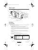
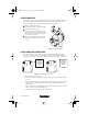
c1937-C-ML.book Page 4 Monday, April 11, 2005 8:06 AM Camera Layout BACK FOCUS ADJUSTMENT MOUNT ADAPTER LOCKING SCREW PHASE ADJUSTMENT LENS LEVEL ADJUSTMENT POWER CONNECTOR COSMETIC TRIM RING BACK FOCUS ADJUSTMENT RING BNC VIDEO CONNECTOR LED LENS CONNECTOR 20156 NOTE: The cosmetic trim ring conceals the LED light for more discreet surveillance operations. The trim ring also hides the power connectors and protects the DIP switches. DIP SWITCHES (COVER REMOVED) Figure 1.
c1937-C-ML.book Page 5 Monday, April 11, 2005 8:06 AM CAMERA MOUNTING Use a standard 1/4-20 screw (provided) with a maximum thread length of 3/8-inch (10 mm) for top or bottom camera mounting. The mount adapter may be fitted to the top or bottom of the camera. The camera is shipped with the mount adapter located on the top of the camera. To change the mount adapter position: 1 Remove the four screws from the mount adapter 2 located on the top of the camera.
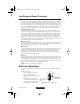
c1937-C-ML.book Page 6 Monday, April 11, 2005 8:06 AM AC operation only - If you are wiring more than one camera to the same transformer, connect one side of the transformer to the same terminal on all cameras, and connect the other side of the transformer to the remaining terminal on all cameras. Failure to connect all of the cameras the same way will cause the cameras to be out of phase with each other and may produce a vertical roll when switching between cameras. Table A.
c1937-C-ML.book Page 7 Monday, April 11, 2005 8:06 AM Lens Setup and Focus Procedures Video Drive Auto Iris Lens Set the lens mode selector switch to AIV. Switch the ESC and AGC OFF. Refer to the lens instructions and adjust the lens for the optimum picture (video output level of 1V peak-to-peak). To focus, fully open the iris by covering the lens with a suitable neutral density (ND*) filter. If the viewed scene is 6.5 feet (2 m) away or farther, set the lens focus to infinity (far).
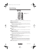
c1937-C-ML.book Page 8 Monday, April 11, 2005 8:06 AM Switch Settings - + L PHASE H LEVEL ON OFF OFF BLC AGC 1 3 OFF OPT ESC AIV AID 5 INT LL OFF NOR OFF OFF AW1 2 NOTE: White indicates switch setting. 4 6 SHP LC 7 EDR 9 8 AW2 10 Figure 6. DIP Switch Default Settings NOTE: Under most conditions, no setting of switches will be required. Please read the details of each switch before making any adjustments.
c1937-C-ML.book Page 9 Monday, April 11, 2005 8:06 AM NOR/SHP - Sharpness NOR (Default setting) - Sets the camera to normal sharpness mode. SHP - Enables the Sharpness mode. Enhances picture detail by increasing the aperture gain of the camera, sharpening the edges in the picture. In some scenes, the SHP mode will increase edge noise on your monitor. LC - Long Line Compensation OFF (Default setting) - Disables the Long Line Compensation mode. LC - Enables the Long Line Compensation mode.
c1937-C-ML.book Page 10 Monday, April 11, 2005 8:06 AM Camera Synchronization (AC Operation Only) When using more than one camera power supply, a brief vertical roll may occur on the monitor when a camera view is switched. To eliminate vertical roll, adjust the phase control by synchronizing, or line-locking, the cameras to one another. Use the phase potentiometer located on the side of the camera (refer to Figure 1) to make adjustments.
c1937-C-ML.
c1937-C-ML.book Page 12 Monday, April 11, 2005 8:06 AM PRODUCT WARRANTY AND RETURN INFORMATION WARRANTY Pelco will repair or replace, without charge, any merchandise proved defective in material or workmanship for a period of one year after the date of shipment. Exceptions to this warranty are as noted below: • Five years on FT/FR8000 Series fiber optic products and the following fixed camera models: CC3701H-2, CC3701H-2X, CC3751H-2, CC3651H-2X, MC3651H-2, and MC3651H-2X.
c1937-C-ML.book Page 13 Monday, April 11, 2005 8:06 AM Instrucciones de Seguridad y Advertencias Importantes Antes de instalar y usar este producto, tenga en cuenta las siguientes ADVERTENCIAS: 1. Lea estas instrucciones. 2. Conserve estas instrucciones. 3. Tenga en cuenta todas las advertencias. 4. Siga todas las instrucciones. 5. No utilice este aparato cerca del agua. 6. Límpielo sólo con un paño seco. 7. No bloquee ninguna abertura de ventilación.
c1937-C-ML.book Page 14 Monday, April 11, 2005 8:06 AM Avisos Reglamentarios Este equipo ha sido probado y se ha determinado que cumple con los límites de un dispositivo digital Clase B, según el apartado 15 de las reglamentaciones de la FCC. Esos límites están diseñados para brindar protección razonable contra interferencia peligrosa en una instalación residencial.
c1937-C-ML.book Page 15 Monday, April 11, 2005 8:06 AM Composición de la Cámara TORNILLO DE BLOQUEO DE AJUSTE DE FOCO DE FONDO ADAPTADOR DE MONTURA AJUSTE DE FASE AJUSTE DE NIVEL DE LENTE SUMINISTRO DE ENERGÍA ELÉCTRICA ANILLO DE GUARNICIÓN COSMÉTICO NOTA: El anillo de guarnición cosmético oculta la luz LED para operaciones de vigilancia más discretas. El anillo de guarnición también oculta los conectores eléctricos y protege los interruptores DIP.
c1937-C-ML.book Page 16 Monday, April 11, 2005 8:06 AM MONTAJE DE LA CÁMARA Use un tornillo 1/4-20 estándar (suministrado) con una longitud de rosca máxima de 3/8 pulgada (10 mm) para montaje en la parte superior o inferior de la cámara. El adaptador de montura se puede colocar en la parte superior o inferior de la cámara. La cámara se envía con el adaptador de montura ubicado en la parte superior de la cámara.
c1937-C-ML.book Page 17 Monday, April 11, 2005 8:06 AM Sólo para suministro CA - Si desea conectar más de una cámara al mismo transformador, conecte un lado del transformador al mismo terminal en todas las cámaras, y conecte el otro lado del transformador al terminal restante en todas las cámaras. Si no conecta todas las cámaras de la misma manera, las cámaras podrían quedar fuera de fase entre sí y se podría producir movimiento vertical de la imagen al cambiar de una cámara a otra. Tabla A.
c1937-C-ML.book Page 18 Monday, April 11, 2005 8:06 AM Lente de iris automático de comando directo (CC) Configure el interruptor del selector de modo de lente en AID (configuración predeterminada). Coloque los interruptores ESC y AGC en posición OFF. Use un destornillador adecuado para girar el potenciómetro de nivel de lente (consulte la Figura 1) totalmente en sentido horario.
c1937-C-ML.book Page 19 Monday, April 11, 2005 8:06 AM Configuración de Interruptores - + FASE L H NIVEL ON OFF OFF BLC AGC 1 3 OFF OPT ESC AIV AID 5 INT LL OFF NOR OFF OFF AW1 2 4 Nota: El blanco indica configuración de interruptores. 6 SHP LC 7 EDR 9 8 AW2 10 Figura 6. Configuración predeterminada de interruptores DIP NOTA: En la mayoría de las condiciones no será necesario configurar interruptores. Lea los detalles de cada interruptor antes de hacer ajustes.
c1937-C-ML.book Page 20 Monday, April 11, 2005 8:06 AM NOTA: Si se aplica corriente CC cuando el interruptor INT/LL está en posición LL, la cámara no funcionará. Cambie el modo a INT. NOR/SHP - Nitidez NOR (configuración predeterminada) - Configura la cámara en el modo de nitidez normal. SHP - Activa el modo Nitidez. Mejora el detalle de la imagen aumentando la ganancia de apertura de la cámara, dando más nitidez a los bordes de la imagen.
c1937-C-ML.book Page 21 Monday, April 11, 2005 8:06 AM Sincronización de Cámara (Sólo para Suministro Ca) Al utilizar más de una fuente de suministro de energía de cámara, se puede producir un breve movimiento vertical de la imagen en el monitor cuando se cambia la vista de una cámara a otra. Para eliminar movimientos verticales de la imagen, ajuste el control de fase sincronizando, o sincronizando en línea, las cámaras entre sí.
c1937-C-ML.
c1937-C-ML.book Page 23 Monday, April 11, 2005 8:06 AM INFORMACIÓN SOBRE GARANTÍA Y DEVOLUCIÓN DEL PRODUCTO GARANTÍA Pelco reparará o reemplazará, sin cargo, toda mercadería que se compruebe que tiene defectos de material o mano de obra, durante un período de un año a partir de la fecha de envío de la mercadería.
c1937-C-ML.book Page 24 Monday, April 11, 2005 8:06 AM Worldwide Headquarters 3500 Pelco Way Clovis, California 93612 USA USA & Canada Tel: 800/289-9100 Fax: 800/289-9150 International Tel: 1-559/292-1981 Fax: 1-559/348-1120 www.pelco.