INSTALLATION MANUAL ® DX9200 Digital Video Recorder and DX9100 Viewstation C634M-D (12/04)
CONTENTS Section Page IMPORTANT SAFETY INSTRUCTIONS . . . . . . . . . . . . . . . . . . . . . . . . . . . . . . . . . . . . . . . . . . . . . . . . . . . . . . . . . . . . . . . . . . . . . . . . . . . . . . . . . . . . . . . 7 REGULATORY NOTICES . . . . . . . . . . . . . . . . . . . . . . . . . . . . . . . . . . . . . . . . . . . . . . . . . . . . . . . . . . . . . . . . . . . . . . . . . . . . . . . . . . . . . . . . . . . . . . 8 DESCRIPTION . . . . . . . . . . . . . . . . . . . . . . . . . . . . . . .
CONNECTING A CM9760-CC1 . . . . . . . . . . . . . . . . . . . . . . . . . . . . . . . . . . . . . . . . . . . . . . . . . . . . . . . . . . . . . . . . . . . . . . . . . . . . . . . . . . . . . . . . CONNECTING A CM6800 . . . . . . . . . . . . . . . . . . . . . . . . . . . . . . . . . . . . . . . . . . . . . . . . . . . . . . . . . . . . . . . . . . . . . . . . . . . . . . . . . . . . . . . . . . . . DATA TRANSLATOR CONFIGURATION . . . . . . . . . . . . . . . . . . . . . . . . . . . . . . . . . . . . . . .
LIST OF ILLUSTRATIONS Figure 1. 2. 3. 4. 5. 6. 7. 8. 9. 10. 11. 12. 13. 14. 15. 16. 17. 18. 19. 20. 21. 22. 23. 24. 25. 26. 27. 28. 29. 30. 31. 32. 33. 34. 35. 36. 37. 38. 39. 40. 41. 42. 43. 44. 45. 46. 47. 48. 49. 50. 51. 52. 53. 54. 55. 56. 57. 58. 4 Page DX9200 System Overview . . . . . . . . . . . . . . . . . . . . . . . . . . . . . . . . . . . . . . . . . . . . . . . . . . . . . . . . . . . . . . . . . . . . . . . . . . . . . . . . . . . . . . . Front View of Recorder . . . . . . . . . . . . . . . .
9. 60. 61. 62. 63. 64. 65. 66. 67. 68. 69. 70. 71. 72. 73. 74. 75. 76. 77. 78. 79. 80. 81. 82. 83. 84. 85. 86. 87. 88. 89. 90. 91. 92. 93. 94. 95. 96. 97. 98. 99. 100. 101. 102. 103. 104. 105. 106. 107. 108. 109. 110. 111. 112. 113. 114. 115. 116. 117. 118. 119. 120. 121. Add Server Window . . . . . . . . . . . . . . . . . . . . . . . . . . . . . . . . . . . . . . . . . . . . . . . . . . . . . . . . . . . . . . . . . . . . . . . . . . . . . . . . . . . . . . . . . . . . Edit Group Window . . . . . . . . .
122. 123. 124. 125. 126. 127. 128. 129. 130. 131. 132. 133. 134. CM9760-REL Configuration Dialog Box . . . . . . . . . . . . . . . . . . . . . . . . . . . . . . . . . . . . . . . . . . . . . . . . . . . . . . . . . . . . . . . . . . . . . . . . . . . . . Change System Location . . . . . . . . . . . . . . . . . . . . . . . . . . . . . . . . . . . . . . . . . . . . . . . . . . . . . . . . . . . . . . . . . . . . . . . . . . . . . . . . . . . . . . . . Select System Location . . . . . . . . . . . . . . . . .
IMPORTANT SAFETY INSTRUCTIONS 1. Read these instructions. 2. Keep these instructions. 3. Heed all warnings. 4. Follow all instructions. 5. Do not use this apparatus near water. 6. Clean only with dry cloth. 7. Do not block any ventilation openings. Install in accordance with the manufacturer’s instructions. 8. Do not install near any heat sources such as radiators, heat registers, stoves, or other apparatus (including amplifiers) that produce heat. 9.
REGULATORY NOTICES This device complies with part 15 of the FCC Rules. Operation is subject to the following two conditions: (1) this device may not cause harmful interference, and (2) this device must accept any interference received, including interference that may cause undesired operation. RADIO AND TELEVISION INTERFERENCE This equipment has been tested and found to comply with the limits of a Class A digital device, pursuant to part 15 of the FCC rules.
DESCRIPTION The DX9200 system consists of at least one digital video recorder (DVR), one viewstation, and one storage unit. The DX9200 digital video recorder can record images simultaneously from as many as 48 cameras at 15 images per second (ips) or from as many as 40 cameras at 30 ips. The DX9200 digital video recorder is compatible with DX9200HDDI storage units.
MODELS DX9100VSR DX9216H DX9232H DX9248H DX9208F DX9216F DX9224F DX9232F DX9240F 10 Viewstation; rack mountable Records at maximum 15 images per second (ips); 16 channels Same as DX9216H, except has 32 channels Same as DX9216H, except has 48 channels Records at maximum 30 ips; 8 channels Same as DX9208F, except has 16 channels Same as DX9208F, except has 24 channels Same as DX9208F, except has 32 channels Same as DX9208F, except has 40 channels C634M-D (12/04)
FRONT VIEW (RECORDER) Rack Ear (2) Handle (2) Fan Ventilation Lock (2 Keys Supplied) Power LED HDD (Hard Disk Drive) LED Fan (2) Power Button 3.5-Inch Floppy Drive Figure 2.
BACK VIEW (RECORDER) Power Supply (2) Power Supply Reset Button AT Keyboard Connector (Not Used) SCSI Connector (2) 37-Pin Connector (Maximum of 6) RS-232 Connector (COM 2) RS-232 Connector (COM 1) RJ-45 Network Connector USB Port for HASP USB Key PS/2 Connector (Keyboard/Mouse) VGA Connector Figure 3.
FRONT VIEW (VIEWSTATION) Power LED HDD (Hard Disk Drive) LED Key Lock (2 Keys Supplied) Fan Ventilation Handles Rack Ears Fan Power Button DVD-RW/CD-RW 3.5-Inch Floppy Drive Figure 4.
BACK VIEW (VIEWSTATION) Power Input (100-240 VAC) PS/2 Connectors (Keyboard/Mouse) Secondary RJ-45 Network Connector USB Ports RS-232 Connector (COM 1) Parallel Port Primary RJ-45 Network Connector Audio Inputs (Line In, Line Out/Headphone, Microphone In) VGA Connectors Modem Connectors RS-232 Connector (COM 2) Figure 5.
INSTALLATION Make sure all parts are present for each unit. Recorder 1 4 2 2 2 1 1 2 1 1 1 1 Recorder Power cords (2 USA standard and 2 European standard) Brackets 6 Screws, 8-32 x .250-inch, pan head Rear mounting rails 8 Screws, 10-32 x .375-inch, flat head Front mounting rails 6 Screws, 8-32 x .375-inch, pan head with washers 4 Screws, 10-32 x .375-inch, flat head Patch panel 1-6 37-pin connector cables 4 Screws, 10-32 x .
INSTALLATION GUIDELINES Follow these guidelines for the best system performance. • The DX9200 recorders require connection to an uninterruptible power supply (UPS) to ensure no corruption of data during a power loss. • The DX9200 system must be installed in a climate-controlled room. The temperature range should be 41° to 85°F (5° to 29°C). • All network devices that will transport DX9200 video must be capable of moving multicast traffic.
MOUNTING The DX9200 recorder and DX9100 viewstation are supplied with the necessary parts for mounting into an industry standard 19-inch (48.26 cm) wide equipment rack. The units can also be placed on a flat surface, such as a shelf. CAUTION: The units should be installed in an air-conditioned room where the temperature is maintained between 41° and 86°F (5° and 29°C). Allow one rack unit (1.75 inches or 4.5 cm) of space between each unit on the rack for air circulation.
To install the unit into an equipment rack: 1. 2. 3. 4. Attach the two brackets to both sides of the unit. Attach the mounting rails to the equipment rack. Place the unit onto the mounting rails. It should slide in and out of the rack easily. Fasten the rack ears to the equipment rack. (8) SCREWS, 10-3 2X .375-INCH, FLAT HEAD REAR MOUNTING RAIL (6) SCREWS, 8-3 2X .375-INCH, PAN HEAD WITH WASHERS FRONT MOUNTING RAIL RACK (4) SCREWS, 10-32 X.
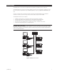
CONNECTIONS Refer to Figure 9. 1. Connect the viewstation and the recorder to an Ethernet switch. Use straight, shielded network cables. NOTE: Use a shielded cable, similar to Belden 1533P, that meets or exceeds the support requirements for ANSI/TIA/EIA 568B.2 Cat 5e. 2. Connect the supplied cables from the 37-pin connectors on the recorder to the 37-pin connectors on the back of the patch panel. NOTE: You will receive 1-6 cables depending on the recorder model you purchase. Figure 7.
VIEWSTATION POWER CONNECTION RJ-45 STRAIGHT CABLE RECORDER 10/100 BASE T ETHERNET INTERFACE: ALLOWS MULTIPLE VIEWSTATIONS AND RECORDERS RJ-45 STRAIGHT CABLE POWER CONNECTIONS HASP KEY PATCH PANEL BACK J1 J2 J3 J4 J5 J6 S1 LOOP E D T E R MIN AT E D 1 2 3 4 5 6 7 8 ON S2 LOOP E D T E R MIN AT E D 1 2 3 4 5 6 7 8 ON S3 LOOP E D T E R MIN AT E D 1 2 3 4 5 6 7 8 ON S4 LOOP E D T E R MIN AT E D 1 2 3 4 5 6 7 8 ON S5 LOOP E D T E R MIN AT E D 1 2 3 4 5 6 7 8 ON S6 LOOP E D T
POWER UP THE EQUIPMENT Follow these steps after you make all connections: 1. Turn on the storage units and let them run for at least one minute (the hard disk drives must spin through their warm-up cycle). 2. Turn on the recorder and let it boot for at least 30 seconds. 3. Turn on the viewstation. The recorder applications start automatically. There are four applications that should be running in order for the recorder to work.
PROGRAMMING VIEWSTATION NETWORK CONFIGURATION After you make all connections, you have to configure the viewstation to work on the network. To configure the viewstation, you need the following information. You can obtain this information from your network administrator. 22 • Unique viewstation name: (Examples are Pelcovs1, Pelcovs2, Pelcovs3, etc. This is the default naming scheme.) • Unique IP address: (Examples are 100.0.0.201, 100.0.0.202, 100.0.0.203, etc. This is the default addressing scheme.
CHANGING THE VIEWSTATION’S IDENTIFICATION To change the default computer name or workgroup: 1. 2. 3. Close all windows on the viewstation desktop. Right-click My Computer and then go to Properties. Click the Network Identification tab. The following page appears. Figure 10. Viewstation Network Identification Page 4. Click Properties. The following dialog box appears. Figure 11. Viewstation Identification Changes Dialog Box 5. 6. 7. C634M-D (12/04) Enter the new computer name or workgroup. Click OK.
CHANGING THE VIEWSTATION’S IP ADDRESS AND SUBNET MASK To change the viewstation’s IP address: 1. Close all windows on the viewstation desktop. 2. Right-click My Network Places and then go to Properties. The following window appears. Figure 12. Viewstation Network Connections Window 3. Double-click Local Area Connection. The following dialog box appears. Figure 13.
4. Click Properties. The following dialog box appears. Figure 14. Viewstation Local Area Connection Properties Dialog Box 5. Make sure the “Show icon in taskbar when connected” checkbox is selected. 6. Double-click Internet Protocol (TCP/IP). The following dialog box appears. Figure 15. Viewstation Internet Protocol (TCP/IP) Properties Dialog Box 7. Enter the IP address (for example, 100.0.0.201). The last three digits must be different for each viewstation (for example, 201, 202, 203, etc.). 8.
CHANGING THE RECORDER’S IDENTIFICATION The recorder name has been preset during manufacturing. The default name is Pelco1. Changing the recorder’s name should be done through the Server Identification dialog box only. 1. 2. Close all applications on the recorder. Double-click the DX9000 Server Configuration Utility icon on the desktop. The following dialog box appears. Figure 16. Server Configuration Utility Dialog Box 3. Click Server Identification. The following dialog box appears. Figure 17.
TIME SYNCHRONIZATION All equipment in your system must have the same time. Pelco recommends you select all recorders as time synchronization recorders. Creating this chain ensures that the system will maintain the correct time in case one or more recorders fail. All recorders and viewstations must belong to the same workgroup or local area network (LAN). Follow these steps for each recorder and each viewstation: 1. 2. Close all applications on the recorder and viewstation.
SETTING DATE/TIME PROPERTIES Follow these steps to set the Date/Time Properties on the recorder and the viewstation. Make sure you close all applications on the recorder and viewstation. 1. Double-click the time on the system tray. The following page appears. Figure 18. Date & Time Page 2. Set the date and time and then click Apply. 3. Click Time Zone. The following page appears. Figure 19. Time Zone Page 4. Select your time zone from the drop-down box.
CLIENT CONFIGURATION UTILITY You can do the following with this utility: • • • • • Synchronize the time between the recorder and the viewstation Identify all the recorders that interface with the viewstation Set the Daylight Saving Time for the viewstation Import and export the server chain list Build a list of local servers 1. Go to Start > Programs > DX9000 Viewstation > Client Configuration Utility. The following dialog box appears. Figure 20. Client Configuration Login Dialog Box 2.
5. Select “Standard naming” or “Custom naming.” a. Standard naming: Select this option if all recorders have the same name and the only difference is the numbers. For example, Pelco1, Pelco2, Pelco3. b. Custom naming: If your recorders have different names, enter the names and then click Add. 6. Click Configure. The following dialog box appears. Figure 22. Export to Server Dialog Box 7. Select “Export to server.” 8. Select the name of the first recorder from the drop-down box. 9. Click Configure.
RECORDER INITIALIZATION OPTIONS To set the recorder initialization options, you must open the DX9000 Server Configuration Utility. 1. Double-click the DX9000 Server Configuration Utility icon on the desktop. 2. Set the “Frame rate & resolution” from the drop-down box. The default is CIF, Half, which is 15 ips at CIF resolution for DX9216H models and 30 ips at CIF resolution for DX9208F models. The following figure shows the options for the DX9216H models. Figure 23.
4. Enter the “Multicast group.” This number is based on the recorder’s IP address. For example, if the IP address is 100.0.0.101, then the multicast group number should be 239.0.0.101. The last three numbers should match. 5. Enter the Multicast TTL number (1-20). This is the number or routers, if any, which separate the recorder from its farthest viewstation on the network. If you do not know the number of routers, contact the network administrator. 6. Enter the “Alarm interval.
SERVER STATE The Server State utility checks the status of the recorders that are connected to the viewstation. It verifies if a recorder is recording, not recording, or unreachable. The Server State application should be running in the background all the time. 1. Go to Start > Programs > DX9000 Viewstation > Server State. Figure 26. Server State C634M-D (12/04) 2. Select “All servers” to run the test on all recorders or “Server” to run the test on a specific recorder. 3. Click Configure.
Figure 27. Configuration Options 4. Select the refresh interval. The recommended setting is 60 seconds. Any setting less than 60 seconds will become network intensive because the viewstation constantly polls the recorders. 5. Click OK. 6. Check the “Auto-refresh” checkbox. The application checks the refresh interval when you click start. 7. Check the “Alert on errors or warning” checkbox. The following message appears when an error occurs. Figure 28. Error Alert 8. Click Start.
ADVANCED RECORDER OPTIONS To set the advanced recorder options, you must open the DX9000 Server Configuration Utility. Double-click the DX9000 Server Configuration Utility icon on the desktop. The Server Configuration Utility dialog box appears with the Advanced Options section. Make sure you close all other desktop applications on the viewstation and recorder. Figure 29. Advanced Options Delete existing info on database: Select the checkbox to restore the database to its initial state. Click Configure.
DATABASE RESTORATION The following procedure explains how to restore a database that has been backed up. 1. 2. Close all recorder applications. Go to the system tray. Figure 31. System Tray 3. Double-click the SQL server icon. The following window appears. Figure 32. Server Service Manager Window 4. Click Stop. The following dialog box appears. Figure 33. Stop SQL Dialog Box 1 5. Click Yes. The following dialog box appears. Figure 34.
6. Click Yes. Start/Continue is enabled after several seconds. NOTE: The SQL Server Agent will be stopped also. It must be restarted later in the procedure. Figure 35. Start/Continue Window 7. 8. Exit the window. Double-click the recorder name icon on your desktop. The following window appears. Figure 36.
9. Go to D:\Databases. The following window appears. Figure 37. Databases Window 10. Rename MSSQL to MSSQL_old. Figure 38.
11. Go to C:\Copy of D Drive\Databases. The following window appears. Figure 39. C Drive Databases Window 12. Copy the MSSQL folder and paste it to D:\Databases. Figure 40. MSSQL Folders 13. Delete MSSQL_old. NOTE: Remember to delete it from your recycle bin also.
14. Double-click the SQL server icon. The following window appears. Figure 41. Start/Continue Window 15. 16. 17. 18. 19. Select SQL Server Agent from the Services drop-down box. Click Start/Continue. Stop is enabled and the status is Running after several seconds. Select SQL Server from the Services drop-down box. Exit the window. Go to E:\DatabaseBackups. The following window appears. Figure 42. Database Backups Window 20. Select the most recent database backup file (Vigilant Server_db). 21.
Figure 43. Explorer Windows 22. Drag the database backup file to C:\AvServer\Config\avRestoreDBR2. The following dialog box appears. Figure 44. Restore Utility Dialog Box 23. Go to the system tray. Figure 45.
24. Double-click the SQL server icon. The following window appears. Figure 46. Server Service Manager Window 25. Click Stop. The following dialog box appears. Figure 47. Stop SQL Dialog Box 1 26. Click Yes. The following dialog box appears Figure 48. Stop SQL Dialog Box 2 27. Click Yes. Start/Continue is enabled after several seconds. Figure 49.
28. 29. 30. 31. Select SQL Server Agent from the Services drop-down box. Click Start/Continue. Stop is enabled and the status is Running after several seconds. Select SQL Server from the Services drop-down box. Exit the window. Figure 50. Replace Database Dialog Box 32. Click OK. The following dialog box appears. Figure 51. Restore Confirmation Dialog Box 33. Click OK to restore from the selected backup file. The following dialog box appears. Figure 52. Operation Completed Dialog Box 34.
Figure 54. Finished Scan Dialog Box 39. Select “Merge files not found on Database” to create new records on the database for the video files that were detected. 40. Select “Delete database records not found on Disk” to delete records on the database that do not have any video files. 41. Click Normalize to merge files and delete records. “Finished Merging” appears at the bottom of the window when the process is complete. Figure 55. Finished Merging Dialog Box 42. Click Close. 43. Restart the recorder.
RAID MANAGER UTILITY The Raid Manager Utility is preinstalled and preprogrammed on all DX9200 recorders and all DX9100 viewstations prior to shipping. The application monitors the health of the DX9200HDDI external hard drive storage unit and provides alarm notification if there is a malfunction. If you have changed recorder names and IP addresses, changed viewstation IP addresses, or added/removed recorders to the system, you must update this utility with the same information.
3. Select Pelco1 and then click Edit Server. The following window appears. Figure 57. Default Server Information Window 4. Enter the new recorder name and IP address. The following example shows the recorder name Orangeburg and the IP address 100.0.0.110. Figure 58. Edit Server Window 5. Click OK. The new recorder name appears. To add a new recorder to the group: 1. 2. Select DX9000_GROUP. Click Add Server. The following window appears. Figure 59. Add Server Window 3.
To edit the group: 1. 2. Select DX9000_GROUP. Click Edit Group. The following window appears. Figure 60. Edit Group Window 3. Enter the new Group Name and then click OK. The new group name appears under ROOT. NOTE: The group name is case sensitive. You can add a new group for systems located remotely. To add a new group: 1. 2. Select ROOT. Click Add Group. The following window appears. Figure 61. Add Group Window 3. Enter the Group Name and then click OK. The added group appears under ROOT.
GATEWAY CONFIGURATION SETTINGS You must set up the events on the Event Notification page. In case of failure, these settings will send a default error message to the viewstation, regardless if the Raid Manager application is open or closed. In the NetSend Setting page, you must enter the IP addresses of all viewstations on the network. Event Notification 1. Select Setting on the Raid Manager Configuration Window. The Event Notification page appears. Figure 62. Event Notification Page 2. 3. 4.
Netsend Setting 1. Click the NetSend Setting tab. The following page appears. Figure 63. NetSend Setting Page 2. 3. 4. 5. 6. C634M-D (12/04) Make sure the NetSend Notify checkbox is selected to activate the net send notification. This is the default setting. Enter the IP address of the additional viewstations. Click Add. Click OK. Restart the viewstation.
VIEWSTATION IP ADDRESS If you change the IP address on the viewstation, you must follow these steps to make sure the Raid Manager Gateway works properly: 1. 2. Right-click the Internet Explorer icon on your viewstation desktop. Select Properties. The following window appears. Figure 64. Internet Properties Window 3. 4. Replace the viewstation IP address in the Address box and then click OK. Do not delete /html/index_win.htm.
5. 6. Double-click the viewstation name under the Internet Information Services tree. Right-click Default Web Site and then select Properties. The following window appears. Figure 66. Default Web Site Properties 7. 8. 9. C634M-D (12/04) Enter the viewstation’s IP address in the IP Address box. Click Apply. Click OK.
RAID MANAGER HOME PAGE After you configure the Raid Manager Gateway, you must go to your web browser. 1. Double-click the Internet Explorer icon on your viewstation desktop. Internet Explorer opens and the Raid Manager home page appears. Figure 67. Raid Manager Home Page NOTE: If the Raid Manager home page does not appear, enter the viewstation IP address in the Address box. Refer to the Viewstation IP Address section. 2. 3. 52 Verify that the recorder names you added or edited are correct.
4. Double-click the name and serial number information. The storage information window appears. Figure 68. Storage Information Window 5. Click Controller Information to see the unit type and details. The following window is an example. Figure 69.
DISK INFORMATION PLATE This screen shows you the status for each of your disks. The disk status appears on each icon. Refer to Table B. Table B. Disk Status Icon Description No hard drive is installed in the disk slot. The hard drive is online and configured. Rebuilding the newly replaced drive. The hard drive in the disk slot is a spare. Hard drive failure. Double-click each icon to see its configuration. The following screenshot shows the disk information of a hard drive that is not installed.
The following screenshot shows the disk information of a hard drive that is online and configured. Figure 71. Configured Hard Drive Information The following screenshot shows the disk information of a hard drive that is rebuilding the newly replaced drive. Figure 72. Newly Replaced Hard Drive Information The following screenshot shows the disk information of a hard drive that is a spare. Figure 73.
HOST AND RAID INFORMATION PLATE This screen shows you the host and raid configuration. You can see the connections between the Lun and Slice on each array. This screen has three columns: • • • Host 1 Interface Raid Information Host 2 Interface Figure 74. Host & Raid Information Screen To see the information for each column: 1. Click the Host 1 Interface Detail button to see the host information. Figure 75. Host 1 Interface Details 2.
Figure 76. RAID Information Details 3. Click the Host 2 Interface Detail button to see the host information. Figure 77. Host 2 Interface Details 4. Move the cursor on the Slice or Lun column to see their logical connection on each array. STATUS PLATE The status plate has four indicators for the raid unit: • • • • Fan Temp Power UPS Figure 78. Status Plate The status plate lets you know whether the fan, temperature, and power are working.
CAMERA RECORDING PROPERTIES Camera recording properties should be set by the system administrator during installation. Only system administrators and operators with a Level 1 authorization can set or change camera recording properties. To set or change camera recording properties, you must open the DX9000 Viewstation application. The System button on the main toolbar is not available to Level 2-6 operators. If you do not have access, see the system administrator.
2. Click “Select channel” to display a list of recorders. An example is shown below. Figure 80. Select Channel Dialog Box 3. Select a channel. 4. Select the Preview checkbox, as shown below, to verify that you have the correct camera. Figure 81.
CONTINUOUS RECORDING SCHEDULE 1. Select the “Continuous recording” radio button. (This is the default setting and should already be selected the first time you select a channel.) Refer to Figure 81. 2. Click Apply. Recording is done at all times and no schedule is defined. The entire daily and weekly recording schedules are marked in light yellow, and any previous definitions on the schedules are removed.
The example below shows a daily Event record schedule from 7:05 a.m. to 12:05 p.m. The box in the time bar is yellow with a red border. You can make the box smaller or larger by dragging it using your mouse. Figure 83. Daily Event Recording Page If you select event recording, the DX9200 actually records continuously. The difference between continuous and event recording is the way the video is saved in the database. When the hard drives are full, the DX9100 starts overwriting the oldest video.
WEEKLY RECORDING SCHEDULE NOTE: To make sure there is no delay during scheduled recording, begin the recording at least five minutes before the actual recording time. For example, schedule a recording at 7:55 a.m. instead of 8:00 a.m. 1. Select the “Weekly recording schedule” radio button. 2. Click Continuous or “Event record.” 3. In the time bars, click the desired start/end times for recording for each day of the week, or enter the exact start/end times in the “Fine tune” fields. 4. Click Apply.
MOTION DETECTION 1. Click the DVMD tab. The DVMD page appears. Refer to Figure 86. 2. Select the “Detector on” radio button. 3. Select the Preview checkbox. The video has blue squares over the entire area meaning the entire video has been selected for motion detection. 4. Click “Clear all” to remove all of the boxes or click the right mouse button on each box you want to remove. 5.
CHANNEL SETUP This section describes how to set camera properties to get the best picture. 1. 2. 3. 4. Click the Video tab. The Video page appears. Refer to Figure 87. Select the Preview checkbox to see the video quality with the default settings. Adjust the video quality by dragging the triangles on the slider bars to the desired values. Refer to Table C. Click Apply. NOTE: The bit rate, located under the “Select channel” button, displays the amount of activity in the specified channel.
Table C. Channel Setup Parameter C634M-D (12/04) Description/Action Channel Name Enter a new name for this channel. You can enter up to 20 characters. Brightness Drag the triangle to change the brightness value. The higher the value, the higher the bit rate. The previous value is displayed to the right of the brightness bar. Contrast Drag the triangle to change the contrast value. The higher the value, the higher the bit rate. The previous value is displayed to the right of the contrast bar.
DEFINING USERS Only system administrators can define user names and passwords for the DX9100 Viewstation. Other users trying to access this option will get the following message: Figure 88. User Access Dialog Box This option allows an administrator to add, delete, and change the properties of users in the DX9200 system. There are seven predefined user access levels ranging from Administrator to Operator Level 6. Each user is assigned different access rights to the DX9200 network and videos.
Table D. User Access Rights User Live Video/ Live Events Video Locked Playback/ Video Query/Sherlock Playback Lock Video Export Image/ Video Unlock Video/ Define Change Camera Users/Audit Settings Viewer Administrator ✓ ✓ ✓ ✓ ✓ ✓ Operator Level 1 ✓ ✓ ✓ ✓ ✓ ✓ Operator Level 2 ✓ ✓ ✓ ✓ ✓ Operator Level 3 ✓ ✓ ✓ ✓ Operator Level 4 ✓ ✓ ✓ Operator Level 5 ✓ ✓ Operator Level 6 ✓ ✓ Edit Existing Users 1. Select the server name from the “Filter per server” drop-down box.
ADVANCED FEATURES I/O INTERFACE The DX9200 system can interface with the CM6800, CM9740, or CM9760 matrix switchers. It can integrate with the CM9760-DT, CM9760-ALM, and CM9760-REL. • • • CM9760-DT data translator translates the ASCII protocol to the P protocol of the CM9740/CM9760 matrix switchers. Connect up to four CM9760-ALM alarm units to each DX9200 recorder. Connect up to four CM9760-REL relay units to each DX9200 recorder.
CONNECTING AN ALARM UNIT You can connect a maximum of four alarm units to a recorder. To connect a CM9760-ALM to a DX9200 recorder using RS-232 communication: 1. Connect a null modem cable from the alarm unit’s RS-232 port to the recorder’s COM 1 or COM 2 port. 2. Set the DIP switches on the alarm unit for RS-232 communication. Refer to the CM9760-ALM Installation/Operation manual. If using RS-422 communication: 1.
ALARM UNIT CONFIGURATION Follow these steps to configure a CM9760-ALM alarm unit. NOTE: This programming is required only on the recorder that is physically connected to the CM9760-ALM. 1. Go to Start > Programs > DX9000 Server > IO Handler Configuration. The following dialog box appears. NOTE: You can also open the I/O Handler from the DX9000 Server Configuration Utility. Figure 91. Alarm I/O Handler Configuration Dialog Box 2.
4. Click Open. The following dialog box appears. Figure 93. Device 2 Alarm Driver Dialog Box 5. Click Configure. The following dialog box appears. Figure 94. CM9760 Alarm Configuration Dialog Box 6. Set the baud rate to 4800. The alarm unit should have this same baud rate. 7. Enter 1 or 2 in the COM Port field. This is the physical port on the recorder that connects to the alarm unit. 8. Set the default interval.
I/O Manager for Alarm Unit 1. Go to Start > Programs > DX9000 Server > IO Manager Configuration. The Overview dialog box appears. NOTE: You can also open the I/O Manager from the DX9000 Server Configuration Utility. 2. Click Next. The following dialog box appears. Figure 95. Dialog Box to Configure External 1 Source 72 3. Select the channel or channels that will receive events from the alarm unit. 4. Enter the server name that the alarm unit is connected to. 5.
7. Click OK. The information you entered appears on the screen, as shown in Figure 96. NOTE: If you click Clear, all configurations for the selected channel are deleted. Figure 96.
8. Click Next. The following dialog box appears. Figure 97. Dialog Box to Configure External 2 Source 9. Follow steps 3-7 if you want to define the second alarm input per camera. 10. Click Next. The Step 3 screen appears. NOTE: The Step 3 and Step 4 screens are used for the relay unit configuration and the data translator configuration. You do not have to enter any information in these screens for the alarm unit configuration. To exit, click Next and then Finish.
CONNECTING A RELAY UNIT To connect a CM9760-REL to a DX9200 recorder using RS-232 communication: 1. Connect a null modem cable from the relay unit’s RS-232 port to the recorder’s COM 1 or COM 2 port. 2. Set the DIP switches on the relay unit for RS-232 communication. Refer to the CM9760-REL Installation/Operation manual. If using RS-422 communication: 1. Connect a cable from the relay unit’s RJ-45 COM IN port to the recorder’s RS-232 port via an RS-232 to RS-422 converter. 2.
RELAY UNIT CONFIGURATION Follow these steps to configure a CM9760-REL relay unit. NOTE: This programming is required only on the recorder that is physically connected to the CM9760-REL. 1. Go to Start > Programs > DX9000 Server > IO Handler Configuration. The following dialog box appears. NOTE: You can also open the I/O Handler from the DX9000 Server Configuration Utility. Figure 99. Relay I/O Handler Dialog Box 2.
4. Click Open. The following dialog box appears. Figure 101. Device 1 Relay Driver Dialog Box 5. Click Configure. The following dialog box appears. Figure 102. CM9760 Relay Configuration Dialog Box 6. Set the baud rate to 9600 and the parity to Even. The relay unit should have these same settings. 7. Enter 1 or 2 in the COM Port field. This is the port on the recorder that connects to the relay unit. 8. Set the default latch time.
I/O Manager for Relay Unit The Step 3 and Step 4 screens in the I/O Manager Configuration are used to finish configuring a relay unit. Step 3 configures the recorder channels with the selected relay ports. Step 4 translates the event type from one type to another. If you are already in the I/O Manager Configuration, follow the steps below. If you are not in the I/O Manager Configuration, go to Start > Programs > DX9000 Server > IO Manager Configuration.
6. Click Next. The following dialog box appears. Figure 104. Dialog Box to Configure Relay Event Type 7. Select the event type to translate. NOTE: Do not select Stop Recording and Start Recording. They are reserved for future use. 8. 9. C634M-D (12/04) Select “No translation.” Click OK and then Finish.
CONNECTING A CM9760-CC1 To connect a CM9760-CC1 to a DX9200 recorder, you must use a CM9760-DT. 1. 2. 3. Connect a null modem cable from the CM9760-DT’s COM A port to the recorder’s COM 1 or COM 2 port. Connect a null modem cable from the CM9760-DT’s COM B port to the COM 1 or COM 2 port on the CM9760-CC1. Set the jumpers in the data translator for baud rate and parity. Refer to the CM9760-DT Installation/Operation manual.
CONNECTING A CM6800 The CM6800 external alarm files must be set up correctly. You must set auto reset on the CM6800 to acknowledge alarms. Refer to the CM6800 Installation/Operation manual. To connect a CM6800 to a DX9200 recorder: 1. 2. 3. Connect a null modem cable from the recorder’s COM 1 or COM 2 port to COM 1 (RS-232) on the CM6800. Set the RS-232 COM 1 port on the CM6800 as ASCII. Set the baud rate on the CM6800 to match the baud rate on the recorder.
DATA TRANSLATOR CONFIGURATION Integrating a data translator serves two functions: • Synchronize time between the DX9200 system and the matrix switcher. • Send ASCII command strings to the matrix switcher (CM6800/CM9740/CM9760) for alarm conditions, such as sending alarms based on motion detection. NOTE: This programming is required only on the recorder that is physically connected to the CM9760-CC1 or CM6800. Follow these steps to configure a data translator unit. 1.
4. Click Open. The following dialog box appears. Figure 109. Device 1 Data Translator Driver Dialog Box 5. Click Configure. The following dialog box appears. Figure 110. CM9760 Relay Configuration Dialog Box 6. Set the baud rate to 4800 and the parity to Even. The data translator should have these same settings. 7. Enter 1 or 2 in the COM Port field. This is the physical port on the recorder that connects to the data translator. 8. Set the Time Synch Update.
I/O Manager for Data Translator The Step 3 and Step 4 screens in the I/O Manager Configuration are used to configure the data translator. Step 3 configures the recorder channels with the selected data translator. Step 4 translates the event type from one type to another. If you are already in the I/O Manager Configuration, follow the steps below. If you are not in the I/O Manager Configuration, go to Start > Programs > DX9000 Server > IO Manager Configuration.
6. Click Next. The following dialog box appears. Figure 112. Dialog Box to Configure Data Translator Event Type C634M-D (12/04) 7. Select the event type to translate. 8. Select “No translation.” 9. Click OK and then Finish.
DVR MANAGEMENT If the DX9200 DVR system is connected to a matrix switcher, the operation of the system can be managed with the Server Alert Configuration Utility. If recorders are not recording or there is no communication with recorders, this utility sends alarms to the matrix switcher. If the DX9200 system is connected to a Pelco matrix switcher, such as the CM9740 or CM9760, alarms are sent through a data translator. For non-Pelco matrix switchers, alarms are sent through a relay unit.
CONFIGURING THE DATA TRANSLATOR 1. Go to Start > Programs > DX9000 Viewstation > Server Alert Configuration Utility. The following dialog box appears. Figure 114. Data Translator Configuration Dialog Box 2. Click Select. The following dialog box appears. Figure 115. Data Translator Driver Dialog Box 3. Select CM9760DT.dll. 4. Click Open. The following dialog box appears. Figure 116. Data Translator Driver Settings Dialog Box 5. Enter the offset number in the Server Alert Settings box.
6. Click Configure. The following dialog box appears. Figure 117. CM9760-DT Configuration 7. Set the baud rate to 4800 and the parity to Even. The data translator should have these same settings. 8. Enter the COM Port number. This is the port on the viewstation that connects to the data translator. 9. Click OK. 10. Click Test. 11. Click OK on the Server Alert Configuration screen to save your settings.
RELAY UNIT CONNECTIONS You can connect up to four relay units to each viewstation. The CM9760-REL should be used with third-party matrix switchers for hard-wired alarm integration. To connect a CM9760-REL to a DX9100 viewstation using RS-232 communication: 1. Connect a null modem cable from the relay unit’s RS-232 port to the viewstation’s RS-232 port. 2. Set the DIP Switches on the relay unit for RS-232 communication. Refer to the CM9760-REL Installation/Operation manual.
CONFIGURING THE RELAY UNIT 1. Go to Start > Programs > DX9000 Viewstation > Server Alert Configuration Utility. Figure 119. Relay Unit Configuration Dialog Box 2. Click Select. The following dialog box appears. Figure 120. Relay Unit Driver Dialog Box 3. Select CM9760REL.dll. 4. Click Open. The following dialog box appears. Figure 121. Relay Unit Driver Settings Dialog Box 5. 90 Enter the relay number in the Server Alert Settings box. The first relay starts with 0.
6. Click Configure. The following dialog box appears. Figure 122. CM9760-REL Configuration Dialog Box 7. Set the baud rate to 9600 and the parity to Even. The relay unit should have these same settings. 8. Enter the COM Port number. This is the port on the viewstation that connects to the relay unit. 9. Change the default latch time. This time activates the relays on the relay unit and sets the same latch time for all of the relay ports. The default is 5 seconds. NOTE: Frame Address is not used.
FOREIGN LANGUAGE PROGRAMMING This programming is applicable to the viewstation only. You can select only the following locations for use with the DX9200 system: • • • • • • • • • English (United States) French (France) German (Germany) Italian (Italy) Polish Portuguese (Brazil) Russian Chinese (PRC) Spanish (Spain) In the example below, the location is changed from the default English (United States) to Spanish (Spain). 1. Double-click My Computer > Control Panel > Regional Options.
4. Click Set Default. The following dialog box appears. Figure 124. Select System Location 5. Select the same location. 6. Click OK. 7. Click Apply. 8. Click Yes to skip file copying and use existing files. 9. Click Yes to restart your computer. The new settings take effect after the computer reboots. The DX9200 will support Spanish settings for numbers, currency, times, dates, menu strings, and text translations.
SERVICE HOW TO REPLACE A RECORDER’S POWER SUPPLY The two power supplies on the back of the recorder are redundant, hot-swappable. When a power supply fails, the green power LED on the power supply turns off and an alarm sounds. Refer to the illustration and steps below. PHILLIPS PAN HEAD SCREW POWER SUPPLY RESET BUTTON POWER CABLE HANDLE POWER SWITCH POWER LED Figure 125. Power Supply Replacement 1. 2. 3. 4. 5. 6. 7. 8. 9. 94 Press the red power supply reset button to turn off the alarm.
HOW TO REPLACE A RECORDER’S RAID 1 DRIVE Before you replace a failed drive, you must open the Promise Array Management Utility to verify which drive has failed. To open the Promise Array Management Utility: 1. Go to Start > Programs > Promise Array Management > Remote Monitoring Utility. The following window appears. Figure 126. Raid Server Window 2. Right-click on the desired recorder name and select Login. (The default recorder name is Pelco 1.) The following window appears.
Figure 128. Remote Monitor Window 5. Double-click FASTTRAK to see FTP1 and Ary1. Figure 129. Fast Trak Window 6. 96 Double-click Ary1 to see the two internal hard drives.
Figure 130. Array Window NOTE: The hard drive icons in Figure 130 show the position of the hard drives in the recorder if looking at the front of the unit. The first hard drive (channel 1) is on the right and the second hard (channel 2) drive is on the left. 7. Select ch2. The following window shows that the second hard drive is functional. Figure 131.
8. Select ch1. The following window shows that the first hard drive is offline and has failed. Figure 132. Drive 1 Status 9. Turn the recorder off and disconnect all cables. 10. Remove the top cover from the recorder. DRIVE CAGE PHILLIPS FLAT HEAD SCREW PHILLIPS PAN HEAD SCREW HARD DRIVE 2 HARD DRIVE 1 Figure 133. Hard Drive Replacement 11. 12. 13. 14. Remove the four Phillips, pan head screws from the top corners of the cage.
16. 17. 18. 19. 20. 21. Slide the new drive into the cage. Tighten the four Phillips, flat head screws with washers. Plug all cables to the hard drives and floppy drive. Place the cage into the chassis and tighten it using the four Phillips, pan head screws. Place the top cover on the recorder. Connect all cables and turn the recorder on. The recorder automatically rebuilds the system array. The Remote Monitoring Utility shows the following. Figure 134.
SPECIFICATIONS RECORDER Electrical/Video Input Voltage: Power Consumption: Signal System: Operating System: Recording Resolution NTSC (DX9200H): PAL (DX9200H): NTSC (DX9200F): PAL (DX9200F): Recording Speed NTSC (DX9200H): PAL (DX9200H): NTSC (DX9200F): PAL (DX9200F): Compression: Video Inputs: 352 x 240 (CIF) at 7.5 or 15 ips 352 x 288 (CIF) at 6.25 or 12.5 ips 352 x 240 (CIF) at 7.5, 15, or 30 ips 704 x 240 (2CIF) at 7.5 or 15 ips 352 x 288 (CIF) at 6.25, 12.5, or 25 ips 704 x 288 (2CIF) at 6.25 or 12.
VIEWSTATION Electrical Input Voltage: Power Consumption: Operating System: Mechanical Connectors 6-pin mini-DIN DB9 DB15 DB15 DB25 RJ-11 RJ-45 USB RCA Hardware Processor RAM Video card Modem Drive General Operating Temperature: Relative Humidity: Dimensions Desktop: Rack-Mount: Unit Weight: C634M-D (12/04) 100-240 VAC, 50/60 Hz, autoranging 90 W maximum Windows 2000 and SP2 Service Pack PS/2 mouse and keyboard Two RS-232 COM ports available for external devices SVGA monitor port (1024 x 768) Composite mo
C634M-D (12/04)
WARRANTY AND RETURN INFORMATION WARRANTY Pelco will repair or replace, without charge, any merchandise proved defective in material or workmanship for a period of one year after the date of shipment. Exceptions to this warranty are as noted below: • Five years on the following fixed camera models: CC3701H-2, CC3701H-2X, CC3751H-2, CC3651H-2X, MC3651H-2, and MC3651H-2X.
® World Headquarters 3500 Pelco Way Clovis, California 93612 USA USA & Canada Tel: 800/289-9100 Fax: 800/289-9150 International Tel: 1-559/292-1981 Fax: 1-559/348-1120 www.pelco.