® ED25/ED2500/ED2620/ED27 Series Environmental Domes Installation/Operation Manual C437M-B (9/95) PELCO • 3500 Pelco Way • Clovis, CA 93612-5699 • USA • www.pelco.
TABLE OF CONTENTS Section Page 1.0 2.0 WARNINGS .......................................................................................................................................1 SCOPE ............................................................................................................................................... 2 2.1 DESCRIPTION ......................................................................................................................... 2 3.0 INSTALLATION ...............
INSTALLATION/OPERATION MANUAL ED25/ED2520/ED2620/ED27/ED2720 SERIES ENVIRONMENTAL DOMES CAUTION: This device is designed to operate at 24 volts AC power. Input voltage must not exceed 28 volts or drop below 22 volts or else DAMAGE TO THE MOTORS WILL OCCUR. Should you need technical assistance, please call (800) 289-9100. 1.0 WARNINGS Prior to installation and use of this product, the following WARNINGS should be observed. 1.
2.0 SCOPE The information contained in this manual covers the ED25/ED2520/ED2620/ED27/ED2720 Series Environmental Domes. The ED25/ED27 Series can be ordered as a dome only or with factory installed heater/blower and service light. Other options include factory assembled integral pan/ tilt and/or Coaxitron/Wiretron receiver/driver. The ED25 Series is designed for flush mount or pendant mount applications. 2.
3.0 INSTALLATION CAUTION: Make certain that the mounting surface is capable of supporting the full load of the mount, pan/tilt, camera/lens and enclosure • Handle the lower dome with care so as not to scratch or get fingerprints on the viewing window. • When installing the unit, loosen the two (2) fasteners and remove the pan/tilt or camera mount to reduce the total weight of the enclosure.
3.1.2 PMED25 Pendant Mount Installation 3.2 To mount the enclosure using the PMED25 pendant mount, perform the following steps. Refer to Figure 3. The following installation instructions are for removing/installing the pan/tilt assembly. 1. 1. The pan/tilt is secured to the back box by two (2) 1/4-20 nuts which hold the pan/tilt mounting bracket to the integral studs on top of the back box. 2.
3.3.2 Conductor Requirements The ED25/ED2520/ED27 Series environmental domes can be connected by a “hard-wire” system, Coaxitron or Wiretron system. The ED2620 Series dome is designed for hard-wire applications only. The distances for each of these system is as follows: Cable Size Hard-wire Systems Max. Cable Distance 14 Awg 16 Awg 18 Awg 20 Awg 22 Awg RG-59U RG-11U RG-6U 680 ft (207.3 m) 425 ft (129.54 m) 265 ft (80.77 m) 165 ft (50.29 m) — — — — Coaxitron System Max.
Figure 5.
ED2620/ED2620-SL Pan/Tilt Wiring Diagram Qty Sym 1 1 1 1 1 14 4 1 1 1 1 C1 C2 M1 M2 J2 – S1-S4 – – – – Description Capacitor, 15 MFD 100 V Capacitor, 15 MFD 100V Pan Motor Tilt Motor Connector Connector Pins Switch Input Connector Mating Connector Actuator Lens Mating Connector Common 1 2 3 4 5 6 7 8 9 10 11 12 Part Number 1 CAPU0015.0/100N CAPU0015.
Figure 7. Wiring Diagram for ED2520/ED2720 Dome Drives Figure 8.
Figure 9. Wiring Diagram for ED2520-PP/ED2720-PP Dome Drives Figure 10.
3.3.3 Video Synchronization, Alarm Terminal Diagram Follow the diagram in Figure 11, for appropriate video synchronization and alarm terminal wiring installation. The following wiring diagram illustrates the configuration of an additional four-position and six-position alarm terminal strip and additional video synchronization connection. These terminal strips are factory installed as standard features on ED2520RX-PP, ED2520SL-RX/PP, ED2720RX-PP and ED2720SLRX/PP models. Figure 11.
4.0 PAN/TILT LIMIT ADJUSTMENTS 5. Loosen the limit stop actuator (shown in Figure 12). Use the joystick to move the tilt table to the maximum tilt-up location and then move the limit stop actuator until it clicks the tilt-up limit switch. Then lock the limit stop actuator by tightening the locking screw. 6. Tilt up and down to verify position of the tilt table. CAUTION: DO NOT attempt to adjust limit stops when the pan/tilt is in operation. Damage to the equipment can result.
5.0 CARE AND MAINTENANCE 6.0 SERVICE AND REPAIR Regularly scheduled maintenance will prolong the operational life and appearance of the equipment. 6.1 RECOMMENDED EQUIPMENT AND TOOLS IMPORTANT: The lower dome of the ED25 environmental dome is an optical surface. When cleaning the inner surface of the dome and viewing window, treat as carefully as you would a fine camera lens. 1. 2. 3. 4. 5. Voltmeter or ohmmeter Allen wrench set Wrench set Screwdriver Pliers, long nose 6.2 SERVICE TIPS 1. 2.
7.0 EXPLODED ASSEMBLY DIAGRAM Figure 14.
8.0 MECHANICAL PARTS LIST The following parts list corresponds to the exploded assembly diagram in Figure 14.
10.0 MODELS ED25 14" diameter environmental dome fixed camera mount. Black opaque lower dome has smoked viewing window (1 f-stop light loss). (CE) ED25-1 Same as ED25 except supplied with service light and heater/blower. ED2520 14"diameterenvironmentaldomewith black opaque lower dome with smoked viewing window and integral pan/tilt. Heater/blower and service light are standard features. (CE, UL) ED2620-PP Same as ED2620 except supplied with preset (PP) pan/tilt.
11.
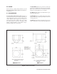
GENERAL Enclosure Max. Camera/Lens Length: Pan/Tilt Maximum Load: Construction: 12.50"L x 4.50"W x 3.25"H (31.75cm x 11.43cm x 8.25cm) Construction: Back Box 0.080" aluminum Viewing Window Optically clear acrylic which has been tinted, rated UL94HB. (Less than 1 f-stop light loss.) Finish: Semigloss beige, self-textured baked enamel Environment: Outdoor Dimensions: See Figure 1 10 lbs (4.6 kg) 0.025" aluminum frame (Product specifications subject to change without notice.) 11.
12.0 WARRANTY AND RETURN INFORMATION WARRANTY RETURNS Pelco will repair or replace, without charge, any merchandise proved defective in material or workmanship for a period of one year after the date of shipment. Exceptions to this warranty are as noted below: In order to expedite parts returned to the factory for repair or credit, please call the factory at (800) 289-9100 or (559) 292-1981 to obtain an authorization number (CA number if returned for credit, and RA number if returned for repair).