I N S T A L L A T I O N EH1512 Series Enclosures EH1512 Enclosure with EM1512 Mount C3453M-C (5/09)
Contents Important Safety Instructions . . . . . . . . . . . . . . . . . . . . . . . . . . . . . . . . . . . . . . . . . . . . . . . . . . . . . . . . . . . . . . . . . . . . . . . . . . . . . . . . . . . . . . . . . . . . 3 Description. . . . . . . . . . . . . . . . . . . . . . . . . . . . . . . . . . . . . . . . . . . . . . . . . . . . . . . . . . . . . . . . . . . . . . . . . . . . . . . . . . . . . . . . . . . . . . . . . . . . . . . . . . . 4 Models . . . . . . . . . . . . . . . . . . . . . . . . . . .
Important Safety Instructions 1. Read these instructions. 2. Keep these instructions. 3. Heed all warnings. 4. Follow all instructions. 5. Do not use this apparatus near water. 6. Clean only with dry cloth. 7. Do not block any ventilation openings. Install in accordance with the manufacturer’s instructions. 8. Do not install near any heat sources such as radiators, heat registers, stoves, or other apparatus (including amplifiers) that produce heat. 9.
Description The EH1512 Series indoor/outdoor enclosures are designed for use with small- to medium-sized analog and IP cameras. They will accommodate both fixed and variable focal length lenses (with or without auto-iris operation). They can be wall mounted using either Pelco’s EM1512 (feedthrough wall mount) or any light to medium duty mount. The tethered, removable enclosure lid provides easy access during installation and when camera and lens adjustments are necessary.
OPTIONAL ACCESSORIES Blower Kit EH1512-1BKIT EH1512-2BKIT EH1512-3BKIT Continuous duty, 120 VAC, 1 W, 1.45 cfm Continuous duty, 24 VAC, 1 W, 1.45 cfm Continuous duty, 230 VAC, 1 W, 1.45 cfm Heater/Blower Kit EH1512-1HBKIT EH1512-2HBKIT EH1512-3HBKIT 120 VAC, 11 W, 1.45 cfm 24 VAC, 11 W, 1.45 cfm 230 VAC, 11 W, 1.45 cfm NOTE: Heaters are thermostatically controlled to turn on at 50°F (10°C) and turn off at 80°F (27°C). The blower operates continuously.
PACKAGE CONTENTS NOTE: A metric Allen wrench (5 mm) is required for installation but is not included. A Phillips screwdriver, flat head screwdriver, or 1/4-inch nut driver is needed for the EH1512-1 and EH1512-3 only. The Allen wrench is needed to open and close the enclosure and to secure the enclosure to all mounts. It is also needed to secure the pan/tilt (swivel head) on the EM1512 mount.
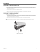
Installation INSTALLING THE OPTIONAL SECURITY KIT The optional security kit (EH-SKIT) contains three tamper-resistant screws and a 1/8-inch hollow screwdriver bit. To install the security kit: 1. Use a 5-mm Allen wrench (not supplied) to remove the three 10-24 x 0.75-inch hex head screws (factory installed) that are located on the enclosure base. (Refer to Figure 2.) 2. Insert the three tamper-resistant screws in the bottom of the enclosure. 3.
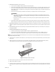
3. Remove the camera sled from the enclosure rail (refer to Figure 3). a. Squeeze the two plastic tabs (located near the front window) that hold the camera sled in place. b. Pull up and slide the sled forward. c. Remove the sled. Figure 3. Removing the Sled 4. Remove the parts bag. This includes the screws, split washers, glands, and nuts. 5. Remove the glands and nuts from the parts bag. 6.
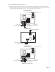
8. (EM1512 mount only) Attach the mount to the wall: a. Use the mount as a template to mark and drill holes in the mounting surface. b. Pull the video and power cables from the wall through the mount. If wiring with conduit, use a step drill to drill a 0.875 inches (2.22 cm) hole in one of the three knockout locations for 1/2-inch conduit. (Knockouts are indicated on the side and bottom of the mount arm.) Refer to Table B on page 11 to determine the size of the power wire needed.
17. Adjust the camera focal length and focus, if necessary. 18. Position the enclosure lid and close it. If using the 10-24 x 0.75-inch hex head screws, tighten them using a 5-mm Allen wrench (not supplied). If using the optional security kit, insert the three tamper-resistant screws (supplied) and tighten them using the 1/8-inch hollow screwdriver bit (supplied). When tightening either kind of screw, ensure that the gasket is properly seated.
INSTALLING THE SUN SHROUD The optional sun shroud fits over the top of the EH1512 enclosure. Perform the following steps to install the sun shroud. 1. Position the front of the sun shroud above the front of the enclosure. 2. Press the sun shroud down and against the enclosure until the sun shroud snaps into place. Table A. Allowable Cable Diameter Gland Cable Diameter PG9 0.181-inch to 0.312-inch PG11 0.230-inch to 0.395-inch NOTE: Conduit must be used if the cable diameter is greater than 0.
Table C. 24 VAC Wiring Distances Wire Gauge Total VA 20 AWG (0.5 mm2) 18 AWG (1.0 mm2) 16 AWG (1.5 mm2) 14 AWG (2.
Specifications MECHANICAL Camera Mounting Single slot for adjustable camera positioning on snap-in camera sled Camera and Lens Size Accepts camera and lens combinations† (including BNC connector) up to 9.00" L x 2.87" W x 3.00" H (22.86 x 7.28 x 7.62 cm) Viewing Window 0.118-inch (3 mm) thick scratch-resistant Lexan® Viewing Area 2.81" W x 2.47" H (7.14 x 6.27 cm) Cable Entry 1 x PG9 and 1 x PG11 compression glands on bottom; PG9 0.312-inch (0.8 cm) and PG11 0.395 (1.
RECOMMENDED CAMERAS AND LENSES Cameras C10CH-6, C10CH-6X, C10CH-7X, C10DN-6, C10DN-6X, C10DN-7X, CCC1390H-6, CCC1390H-6X, IP3701H-2, IP3701H-2X, IXS0C, IXS0DN, IX10C, IX10DN, IXE20C, IXE20DN, IX30C, IX30DN Lenses 13VD2.8-12, 13VD3-8, 13VD5-40, 13VD5-50, 13VDIR2.8-11, 13VDIR3-8.5, 13VDIR7.5-50 NOTE: These lenses are for use with all cameras except Pelco IP cameras with Sarix™ technology. Refer to the specific camera specification sheet for information on recommended lenses.
PRODUCT WARRANTY AND RETURN INFORMATION WARRANTY Pelco will repair or replace, without charge, any merchandise proved defective in material or workmanship for a period of one year after the date of shipment.
www.pelco.com Pelco, Inc.