® WW57 Series Window Wiper Kit for EH5700 Series and EH5700L Legacy® Series Enclosures Installation/ Operation Manual C1432M-C (11/99) Pelco • 3500 Pelco Way, Clovis • CA 93612-5699 USA • www.pelco.
CONTENTS Section Page IMPORTANT SAFEGUARDS AND WARNINGS ................................................................ 3 DESCRIPTION ................................................................................................................... 4 MODELS .................................................................................................................... 4 INSTALLATION ...................................................................................................................
IMPORTANT SAFEGUARDS AND WARNINGS Prior to installation and use of this product, the following WARNINGS should be observed. 1. Installation and servicing should only be done by qualified service personnel and conform to all local codes. 2. Unless the unit is specifically marked as a NEMA Type 3, 3R, 3S, 4, 4X ,6 or 6P enclosure, it is designed for indoor use only and it must not be installed where exposed to rain and moisture. 3. Only use replacement parts recommended by Pelco.
DESCRIPTION Window wiper kits in the WW57 Series are for installation in the EH5700 Series and EH5700L Legacy® Series environmental enclosures.
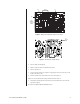
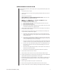
D1-D6 R2 C3 JP1 ADD GREEN WIRE HERE Figure 2. Wiper Circuit Board Component Locations PCB9000275 REV. E X CUT TRACE HERE P14719 Figure 3. Circuit Side of Wiper Board 2. Remove diodes D1 through D6. 3. Replace resistor R2 with a 1/4-watt 470-ohm resistor. 4. Remove capacitor C3. 5. Connect an 18-inch (45.72 cm) length of 22-gauge green wire to the hole in the circuit board for the anode of D3. 6. Turn the circuit board over and cut the trace as shown in Figure 3.
1–2 1–2 JP4 JP5 1–2 2–3 DELAY ON DELAY OFF 2–3 2–3 2–3 2–3 1–2 1–2 INPUT 100 VAC JP3 JP6 1 2 3 4 5 6 2–3 2–3 2–3 2–3 1–2 1–2 2–3 2–3 INPUT 230 VAC 110–220 JP3 110–220 JP2 INPUT 115 VAC JUMPERS JP2 INPUT 24 VAC GRN WIRE TO LENS COMMON P4 3 2 1 CUT TRACE 1 2 3 JP1 1 2 3 3 2 1 CHANGE TO 470Ω YEL VIO BR P1 JP4 R2 4.7K D3 D2 D1 D6 D5 D4 RV2 U1 +5 D23 D21 R5 10K D13 D19 D12 D18 6.
WINDOW WIPER KIT INSTALLATION For the following instructions, refer to Figure 10, if necessary. Table B lists the parts shown in Figure 10. 1. Turn off power to the enclosure. 2. Unlatch and raise the enclosure lid. The gas spring will hold the lid in place when it is fully opened. 3. Remove the camera and sled. 4. EH5723/EH5723L and EH5729/EH5729L Models Only - Remove the vent grill inside the enclosure at the rear of the unit. 5.
Slide the flange bearing over the bearing pin. Switch Pin Bearing Pin Flange Bearing Drive shaft. Cam Flex coupler. Cam Track Drive Shaft Allen cap screws After joining the drive shaft and the drive arm on the wiper assembly with the use of the flex coupler, secure the drive assembly by tightening the Allen cap screws in the coupler. Figure 5. Wiper Drive Shaft Installation Figure 6.
15. Remove the two screws on the bottom of the enclosure under the window and install the wiper assembly with two Allen cap screws that are supplied in the parts bag. Make sure the shaft of the wiper arm goes through the green bushing on the front of the enclosure. 16. Looking at the front of the enclosure from the outside, position the wiper blade so that it is on the left side of the window as you look at it. 17.
If you are installing the wiper kit in a Legacy enclosure, power for the wiper is supplied through the 37-pin connector on the pan/tilt unit as follows: AC High AC Neutral Wiper On/Off Control Pin 15 Pin 16 Pin 25 If you are installing the wiper kit in a non-Legacy unit, power for the wiper is supplied as follows: AC High AC Neutral Wiper On/Off Control Pin 1 of TB2 on the O/I-PCB circuit board (refer to Figure 8) Pin 2 of TB2 on the O/I-PCB circuit board Pin 1 of TB3 on the O/I-PCB circuit board Pins 1
Figure 8. Component Locations for Optional Circuit Board (O/I-PCB) Figure 9.
Table A. 24 VAC Wiring Distances The following are the recommended maximum distances for 24 VAC applications and are calculated with a 10-percent voltage drop. (Ten percent is generally the maximum allowable voltage drop for AC-powered devices.
6 4 A SUPPLIED WITH BLOWER KIT 16 Figure 10.
Table B.
MAINTENANCE As necessary, clean the window with a mild non-abrasive detergent in water and a soft cloth to maintain picture clarity. To order replacement wiper blades, use the part number WW570010050 (3 inches). SERVICE MANUAL If you need to service the wiper assembly, obtain a service manual in one of the following ways: • • Pelco Manual C1432M-C (11/99) Go to Pelco’s web site at ftp://www.pelco.com and find service manual C1431SM.PDF.
PRODUCT WARRANTY AND RETURN INFORMATION WARRANTY Pelco will repair or replace, without charge, any merchandise proved defective in material or workmanship for a period of one year after the date of shipment. Exceptions to this warranty are as noted below: • Five years on FT/FR8000 Series fiber optic products. • Three years on Genex ® Series products (multiplexers, server, and keyboard).