® EH66/EH66X Environmental Enclosures Installation/Operation Manual C411M-D (1/96) Pelco • 3500 Pelco Way, Clovis, CA 93612-5699 • USA • www.pelco.
TABLE OF CONTENTS Section Page 1.0 WARNINGS ........................................................................................................................................ 1 2.0 SCOPE ...............................................................................................................................................2 3.0 DESCRIPTION ...................................................................................................................................2 3.
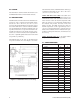
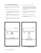
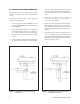
LIST OF ILLUSTRATIONS Figure Page 1 EH66/EH66X Dimension Drawing ................................................................................................. 2 2 Wiring Diagram for Window Defroster, Wiper/Washer and Blower/Heater Assemblies ................. 4 3 EH66 Enclosure with Wall Mount .................................................................................................. 5 4 EH66 Enclosure with Pedestal/Ceiling Mount ..........................................................
This page intentionally left blank.
INSTALLATION/OPERATION MANUAL MODEL EH66/EH66X SERIES ENVIRONMENTAL ENCLOSURES 1.0 WARNINGS Prior to installation and use of this product, the following WARNINGS should be observed. 1. Installation and servicing should only be done by Qualified Service Personnel and conform to all local codes. 2. Unless the unit is specifically marked as a NEMA Type 3, 3R, 3S, 4, 4X, 6, or 6P enclosure, it is designed for indoor use only and it must not be installed where exposed to rain and moisture. 3.
2.0 SCOPE The information contained within this manual covers the EH66/EH66X Series environmental enclosure. 3.0 DESCRIPTION The EH66 Series is an all-weather environmental enclosure for 2/3" and 1" cameras with a maximum camera/ lens size of 7" W x 7" H x 22" L (17.7 cm x 17.7 cm x 55.8 cm). Rugged all aluminum construction protects the camera from adverse weather conditions. Built-in sun visor shields the lens from direct sunlight, and a vent cap allows heated air to escape from the interior.
4.0 INSTALLATION NOTE: Cameras with a low optical centerline or using a large diameter lens require an elevation block (1 inch or 2 inch) for proper positioning. See Section 8.0, Optional Accessories, for the correct model number. Please check the contents of your package(s) for the following items before proceeding with the installation of the equipment. Quantity Item 3. 2 1/4-20 x .
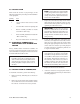
to control Figure 2.
4.3 FIXED ENCLOSURE MOUNTING 3. Attach the adjustable head to the mount. The are two types of mounts that can be used with the EH66 enclosure: wall, or pedestal/ceiling (see Figures 3 and 4). 4. Align the 1/4-20 threaded holes in the bottom of the EH66 enclosure with the holes in the tilt table of the adjustable head. Fasten the enclosure to the table using 1/4-20 fasteners (not to exceed 5/8" in length, minimum two (2).
4.4 PAN/TILT ENCLOSURE MOUNTING 4. Attach the pan/tilt to the mount. The pan/tilt control connect should be positioned towards the building/ mounting location. Note the “front” label on the pan/tilt. 5. If you have not already done so, install the camera/lens according to the instructions in Section 4.2 of this manual. 6. Balance the enclosure/camera/lens load on the tilt table. Adjust the positioning as needed to align the mounting holes. A minimum of two 1/4-20 x 5/8" fasteners must be used.
4.5 WINDOW WIPER INSTALLATION 8. Attach the water reservoir bottle to the rear of the EH66 enclosure by removing the two (2) top acorn nuts. 9. Place the bottle mount on the protruding studs and replace the acorn nuts. To install the window wiper kit, perform the following steps and refer to Figures 7 and 8: 1. Turn the EH66 enclosure over so the bottom is facing up. 2. If necessary, lay out the locations of the four (4) .171-inch diameter mounting holes using the dimensions given in Figure 8. 4.
4.6 B66KIT/E624HB/H66KIT INSTALLATION All heater and blower kits are supplied partially assembled. Install in the enclosure according to the following instructions: 1. Remove the round cap on the rear of the enclosure and the two (2) 8-32 screws and nuts located on each side of the opening above the horizontal line. 2. Remove the two (2) acorn nuts holding the air box to the heater/blower assembly; remove the air box. 3.
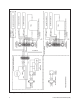
6.0 EXPLODED ASSEMBLY DIAGRAMS See Figures 9 and 10 for exploded assembly diagrams of the EH66 enclosure and WW66, WW66-5/220 wiper assembly. Figure 9.
NOTE: FIGURE DOES NOT REPRESENT CURRENT PUMP IN USE. Figure 10.
7.0 MECHANICAL PARTS LISTS 7.1 MECHANICAL AND ELECTRICAL PARTS LIST FOR EH66 ENCLOSURE Item No. Qty Description 15 16 17 18 19 20 21 22 23 24 25 26 27 28 29 4 1 1 2 2 2 4 8 1 1 1 1 1 1 1 1 2*, 1** 1 4 2 1 1 1 1 1 1 1 1 2 1 2 Gasket, Window Frame Gasket, Cable Entry Plate, Cable Entry Gasket, Rim Gland, UL, PG-13.5 black Nut, UL Gland, 13.
7.2 MECHANICAL PARTS LIST FOR WW66 AND WW66-5/220 WINDOW WIPER ASSEMBLY Item No. Qty 1 2 3 4 5 6 7 8 9 10 11 12 13 14 15 16 3 1 — 1 1 1 1 12 42 1 3 1 1 1 1 1 17 18 19 20 21 22 23 24 25 26 27 1 1 1 1 1 1 2 1 2 1 1 1 1 12 Description Bearing Diode Not used Switch Spacer, 1/4" Hex x .6254-40 tap Transformer Pump Tubing, Vinyl, 1/8 ID x 1/4 OD x in. Tubing, Vinyl, 1/4 ID x 3/8 OD x in.
8.0 OPTIONAL ACCESSORIES FACTORY INSTALLED EHRC Relay module for low voltage control of wiper/washer and camera on/off. Requires MEH24DT control module. TI66 Thermal insulation provides increased thermal protection for enclosure and contents at extreme temperatures (for model EH66 series only). T166X Thermal insulation for model EH66X series.
9.1 RECOMMENDED CABLE SIZE 9.2 POWER REQUIREMENTS FOR BLOWER, HEATER, ACCESSORIES CAUTION: When a single power source is used for both the camera and accessories, the camera power consumption must be taken into consideration when determining the wire gauge. The blower, heater and electrically powered accessories use the following wattage when in operation: The following cable sizes are the minimum recommended for use with the combination of defroster/ blower/heater/camera.
10.0 WARRANTY AND RETURN INFORMATION PRODUCT WARRANTY AND RETURN INFORMATION WARRANTY Pelco will repair or replace, without charge, any merchandise proved defective in material or workmanship for a period of one year after the date of shipment. Exceptions to this warranty are as noted below: • Five years on FT/FR8000 Series fiber optic products. • Three years on Genex ® Series products (multiplexers, server, and keyboard).
® Pelco 3500 Pelco Way, Clovis, CA 93612-5699 • (559) 292-1981 • (800) 289-9100 FAX (559) 292-3827 • (800) 289-9150 • www.pelco.com International customers call 1-559-292-1981 or FAX 1-559-348-1120 (Product specifications subject to change without notice.