® Installation/Operation MC3500/MC3600 Series Monochrome Cameras C1982M-A (12/00) Pelco • 3500 Pelco Way • Clovis, CA 93612-5699 USA • www.pelco.
[2] Pelco Manual C1982M-A (12/00)
CONTENTS IMPORTANT SAFEGUARDS AND WARNINGS ................................................................................. 4 REGULATORY NOTICES .................................................................................................................... 4 DESCRIPTION .................................................................................................................................... 5 Models .............................................................................................
IMPORTANT SAFEGUARDS AND WARNINGS Prior to installation and use of this product, the following WARNINGS should be observed. 1. Installation and servicing should only be done by qualified service and installation personnel. 2. Installation shall be done in accordance with all local and national electrical and mechanical codes utilizing only approved materials. 3. Use only installation methods and materials capable of supporting four times the maximum specified load. 4.
DESCRIPTION The MC3500 and MC3600 Series are compact, monochrome video cameras with a 1/3-inch CCD imager. All cameras have a direct drive/auto iris lens connector and adjustable back focus, and accept C and CS lenses. Models MC3500S-2 MC3500S-2X MC3600H-2 MC3600H-2X Standard resolution, 330 TV lines, HyperHAD™ CCD, 1.0 lux at f1.2, EIA Standard resolution, 380 TV lines, Hyper HAD+ CCD, 0.1 lux at f1.2, CCIR High resolution, 480 TV lines, EXview HAD CCD™, 1.0 lux at f1.
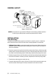
CAMERA LAYOUT BACK FOCUS ADJUSTMENT LOCKING SCREW MOUNT ADAPTER PHASE ADJUSTMENT LEVEL ADJUSTMENT POWER SUPPLY COSMETIC TRIM RING BACK FOCUS ADJUSTMENT RING BNC VIDEO CONNECTOR LENS CONNECTOR LED DIP SWITCHES Figure 1. Camera Layout NOTE: The cosmetic trim ring conceals the LED light for more discreet surveillance operations. The trim ring also hides the power connectors and protects the DIP switches.
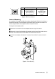
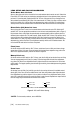
3 1 4 2 PIN DD LENS CONNECTIONS AI LENS CONNECTIONS 1 2 3 4 Control coil negative (-) Control coil positive (+) Drive coil positive (+) Drive coil negative (-) Not used Lens positive supply Video drive signal Ground Figure 2. DD/AI Lens Connector Camera Mounting Use a standard 1/4-20 screw (provided) with a maximum thread length of 3/8-inch (10 mm) for top or bottom camera mounting. The mount adapter may be fitted to the top or bottom of the camera.
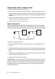
POWER AND VIDEO CONNECTIONS To connect the camera power and video do the following: 1. Remove the rear cover from the camera (refer to Figure 1). Thread cabling through the rear cover. 2. Connect the power cable to the two pin power connector on the back of the camera using the terminal block connector provided. Refer to Table A for the recommended wire gauge to use for the installation 3. Connect a video cable to the SIGNAL OUT connector (BNC) on the back of the camera.
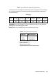
Table A. Recommended Wire Gauge and Wiring Distances The following are the recommended maximum distances for 24 VAC applications and are calculated with a 10-percent voltage drop. (Ten percent is generally the maximum allowable voltage drop for AC-powered devices.) Wire Gauge Total vA 20 (0.5 mm2) 18 (1.0 mm2) 16 (1.5 mm2) 14 (2.5 mm2) 12 (4.0 mm2) 10 (6.
LENS SETUP AND FOCUS PROCEDURES Video Drive Auto Iris Lens When a video drive auto iris lens is used, the lens mode selector switch must be set to AI. Switch the EI and AGC OFF. Refer to the lens instructions and adjust the lens for the optimum picture (video output level of 1V peak-to-peak). Switch the AGC ON. To focus, fully open the iris by covering the lens with a suitable neutral density (ND*) filter. If the viewed scene is 6.5 feet (2 m) away or farther, set the lens focus to infinity (far).
BACK FOCUS ADJUSTMENT The back focus adjustment is located at the front of the camera and is accessible from either side of the case. To adjust the back focus: 1. Loosen the two back focus locking screws (one on each side). 2. Turn the back focus ring: a. Clockwise - Moves the CCD sensor assembly towards the back of the lens. b. Counterclockwise - Moves the CCD sensor away from the lens. 3. When the back focus adjustment is satisfactory, tighten the locking screws.
SWITCH SETTINGS WHITE REPRESENTS SWITCH POSITION 10 9 8 7 6 5 4 3 2 1 Figure 7. Switch Settings 10 LL/INT Synchronization Selection Locks the frame rate to the power supply frequency. Eliminates vertical roll caused by multiple cameras connected to the same switching device. Each camera output is synchronized to the frequency of the power supply. Set the camera synchronization mode to one of the following: Line Lock (LL) - Line-locks frame rate of cameras. INT - Disables line lock.
4 EI ON/EI OFF (Electronic Iris) The EI (Electronic Iris) feature compensates for an excessive light level by automatically adjusting shutter speed. When the EI is ON, the DD lens level potentiometer on the side of the camera may be used to adjust the EI threshold level. The level is factory set to 1V peak-to-peak. OFF - Disables the Electronic Iris mode. Use with auto iris/direct 4 OFF drive lenses. 4 EI ON (Default setting) - Enables the Electronic Iris mode. Use with fixed or manual iris lenses.
CAMERA PHASE ADJUSTMENT When using one AC power supply in a multi camera system, a brief vertical roll may occur on the monitor each time a camera view is switched. To eliminate vertical roll, adjust the phase control to synchronize (line-lock), the cameras to one another. The synchronization switch (DIP switch 10) for each camera must be set to LL. Use the potentiometer located on the side of the camera to make adjustments.
SPECIFICATIONS GENERAL CCD Sensor: Synchronization System: Horizontal Resolution MC3500S-2: MC3600H-2: Iris Control: Minimum Illumination MC3500S-2: MC3600H-2: Signal-to-Noise Ratio Gain Control: Vertical Phase: Automatic Gain Control: Backlight Compensation: Scanning System Auto Iris Lens Type: Video Output: Iris Control Range 1/3-inch AC line lock or internal oscillator 380 TV lines 570 TV lines Electronic/passive 0.1 lux at f1.2 0.05 lux at f1.
PRODUCT WARRANTY AND RETURN INFORMATION WARRANTY Pelco will repair or replace, without charge, any merchandise proved defective in material or workmanship for a period of one year after the date of shipment. Exceptions to this warranty are as noted below: • Five years on FT/FR8000 Series fiber optic products. • Three years on Genex® Series products (multiplexers, server, and keyboard).