® PP351/PP451 Roof Mount Installation/ Operation Manual C263M (7/97) Pelco • 3500 Pelco Way, Clovis, CA 93612-5699 • USA • www.pelco.
CONTENTS Section Page 1.0 GENERAL .................................................................................................. 1 1.1 IMPORTANT SAFEGUARDS AND WARNINGS ............................... 1 1.2 UNPACKING INSTRUCTIONS .......................................................... 2 1.3 RECOMMENDED TOOLS ................................................................. 2 2.0 DESCRIPTION .......................................................................................... 3 2.1 MODELS .....
1.0 GENERAL 1.1 IMPORTANT SAFEGUARDS AND WARNINGS Prior to installation and use of this product, the following WARNINGS should be observed. 1. Installation and servicing should only be done by Qualified Service and Installation Personnel. 2. Installation shall be done in accordance with all local and national electrical and mechanical codes utilizing only approved materials. 3. Use only installation methods and materials capable of supporting four (4) times the maximum specified load. 4.
1.2 UNPACKING INSTRUCTIONS Unpack and inspect all parts carefully. The following parts are supplied: 1 1 1 PP350 or PP450 arm (includes end cap and clamp bracket with attached indexing bolts) Mounting base Installation/Operation Manual (C263M) Be sure to save the shipping carton and any inserts. They are the safest material in which to make future shipments.
2.0 DESCRIPTION The PP351 Roof Mount has been engineered specifically for use with Pelco’s Spectra™ pendant domes. The PP451 has been engineered specifically for use with Pelco’s Intercept™ pendant domes. Both mounts, however, will accommodate any style dome enclosure that uses 1-1/2" NPT pipe for vertical surface mounting. The arm on both mounts swivels, allowing the arm to swivel over the rooftop for installation and maintenance, and to swing away from the roof for surveillance.
3.0 INSTALLATION CAUTION: Make sure that the installation method and fasteners can support up to four times the weight of the mount, dome, and camera. 1. Drill holes in the roof for mounting the base, using the base as a template. It is recommended that you use a minimum of any three of the five possible holes on each side of the base. 2. Attach the mount to the roof with a minimum of eight (8) 3/8-16 type hardware (not supplied).
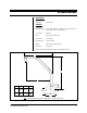
4.0 SPECIFICATIONS MECHANICAL Positioning Adjustment: Unlimited 360° GENERAL Suggested Mounting Method: Secure with a minimum of eight (8), 3/8" fasteners (not supplied) suitable for the mounting surface Construction: Aluminum Finish: Gray polyester powder coat Environment: Indoor/outdoor Maximum load: 45 lbs (20.41 kg) Weight: Approximately 15 lbs (6.80 kg) Dimensions: See Figure 1 (Design and product specifications subject to change without notice.) A B C A B C PP351 25.41 (64.
5.0 WARRANTY AND RETURN INFORMATION WARRANTY Pelco will repair or replace, without charge, any merchandise proved defective in material or workmanship for a period of one year after the date of shipment. Exceptions to this warranty are as noted below: • Five years on FT/FR8000 Series fiber optic products. • Three years on Genex® Series products (multiplexers, server, and keyboard).