® SB26/SB2600 Discreet Surveillance Domes Installation/ Operation Manual C1402M-B (2/98) Pelco • 3500 Pelco Way, Clovis • CA 93612-5699 USA • www.pelco.
CONTENTS Section Page 1.0 GENERAL .................................................................................................. 5 1.1 IMPORTANT SAFEGUARDS AND WARNINGS ............................... 5 2.0 DESCRIPTION .......................................................................................... 6 2.1 Models ................................................................................................ 7 3.0 INSTALLATION ...................................................................
LIST OF ILLUSTRATIONS Figure 1 2 3 4 5 6 7 8 9 10 11 12 13 14 15 16 17 Page SB2600 Wiring Diagram .................................................................... 9 SB2600-SL Wiring Diagram .............................................................. 10 SB2600SL-PP Wiring Diagram ......................................................... 11 SB2600-PP Wiring Diagram ............................................................. 12 Fixed Ceiling Mounting ..................................................
(This page intentionally left blank.
1.0 GENERAL 1.1 IMPORTANT SAFEGUARDS AND WARNINGS CAUTION: This device is designed to operate at 24 volts AC power. Input voltage must not exceed 28 volts or drop below 22 volts or else DAMAGE TO THE MOTORS WILL OCCUR. Should you need technical assistance, please call (800) 289-9100. Prior to installation and use of this product, the following WARNINGS should be observed. 1. Installation and servicing should only be done by Qualified Service Personnel and conform to all Local codes. 2.
2.0 DESCRIPTION The SB26 is a discreet surveillance, low profile, hemisphere dome for CCD type cameras designed for ease of installation, relocation, and service in fixed ceilings or standard 2' x 2' (.61 m x .61 m) or 2' x 4' (.61 m x 1.22 m) false ceiling tiles. The black opaque lower dome effectively conceals the camera while providing an inconspicuous viewing window. The dome is attached to the drive to keep the viewing window and camera aligned.
2.1 MODELS NOTE: All of the models are listed SB26 Drop ceiling discreet surveillance enclosure with black opaque lower dome with 1 f-stop light loss and all aluminum back box which mounts above the ceiling. (Camera mount supplied.) (UL) SB26-1 Same as SB26 except supplied with clear viewing slot for virtually zero light loss. (UL) SB26-2 Same as SB26 except supplied with mirrored lower dome with 2 f-stop light loss.
3.0 INSTALLATION Save the shipping box and any inserts in case the unit must be returned for credit or repair. 3.1 CONDUCTOR AND CABLE REQUIREMENTS (ALL MODELS EXCEPT SB26) A minimum of 12 conductors plus coax is required, which includes common requirements for motorized zoom lens and camera AC power. NOTE: The following are cable requirements. A relay box (RB24) is available to extend the operating distance up to 13,000 feet (3962.4 m) over 16 Awg wire. Non-PP Models 12 Conductor 20 Awg 130 ft (39.
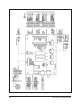
Figure 1.
Figure 2.
Figure 3.
Figure 4.
3.3 MOUNTING INSTRUCTIONS Handle the lower dome with care so as not to scratch or get fingerprints on the viewing window. Determine the type of mounting desired. The enclosure can be mounted in a fixed ceiling, or completely replace a standard 2' x 2' (.61 m x .61 m) ceiling tile. 3.3.1 Fixed Ceiling Mounting To mount the enclosure directly into a fixed ceiling, perform the following steps (refer to Figure 5): 1. Determine the location and direction of the enclosure.
3.3.2 Dropped Ceiling, Tile Replacement Mounting To mount the enclosure into a dropped ceiling grid, perform the following steps (refer to Figure 6): IMPORTANT: When installing the 1. enclosure in a 2' x 4' (.61 m x 1.22 m) ceiling grid, cut the ceiling tile in half and install an additional “T” bar for support. Determine the location for mounting the enclosure and remove the appropriate ceiling tile. 2. Remove trim ring and dome.
3.3.3 Camera/Lens Installation Install the camera/lens that you have selected for use with the SB2600 Series dome as follows: NOTE: Remove “shipping bracket” at this time. Refer to Figure 14, item 65. NOTE: Fixed speed units must 1. Loosen the 1/4-20 lens support fastener and slide lens support down (see Figure 8). 2. Place camera/lens atop the tilt table and thread the provided 1/4-20 x 1/2-inch fastener through the tilt table into the camera (see Figure 8).
3.4 CONNECTOR ASSEMBLY Assemble the connector parts according to the instructions below. Detail B, below, reflects the pin arrangement specific to all SB26/SB2600 Series. Refer to Figure 10 during assembly. For best results use an AMP style crimper when making the wire to pin connection. The instructions that follow apply to all AMP style connectors regardless of pin size or pin number. 1" 1. Slide the connector clamp assembly over the conductor cable.
3.5 J-BOX INSTALLATION For installations requiring full plenum rating, perform the following step: Installations Requiring Conduit When conduit must be run to the enclosure back box: 1. Attach the provided J-box to the top of the enclosure back box as shown in Figure 11 using the supplied 6-32 screws. 2. Remove one of the knockouts from the J-box and attach the conduit to the J-box (hardware not supplied). 3. Run the cabling through to the conduit. 4.
Figure 11.
3.6 ADJUSTMENTS CAUTION: Do not at- tempt to adjust limit stops when the pan/tilt is in operation. Damage to the equipment can result. Do not operate pan/tilt without limit stops. To adjust the pan limits, perform the following steps. Refer to Figure 12 for limit stop locations. Factory pan limits are set at 0-355°, tilt limits are set at 0-90° (horizontal to vertical). To adjust limit stops, perform the following steps: 1.
4.0 MAINTENANCE Clean the acrylic dome as necessary to maintain a clear picture. Be careful not to scratch the surfaces of the dome. Exterior Surface - Clean the dome's exterior surface with a nonabrasive cleaning cloth and cleaning agent that is safe for acrylic plastic. Either liquid or spray cleaner/ wax suitable for fine furniture is acceptable. Interior Surface (Except Chrome) - Clean the same as the exterior surface. Interior Surface (Chrome) - The inside surface of a chrome dome is easily scratched.
5.0 EXPLODED ASSEMBLY DIAGRAMS Refer to Figure 13 for an exploded assembly diagram of the SB26 Enclosure, Figures 14 and 15 for the SB2600 Series Pan/Tilt, and Figure 16 for the SB26 fixed mount. Figure 13. SB26 Exploded Assembly Diagram Table A.
Figure 14.
Table B. SB2600 Series Pan/Tilt Exploded Assembly Parts List Item No.
Table B SB2600 Series Pan/Tilt Exploded Assembly Parts List (continued) Item No.
Figure 15.
Table C. SB2600 Hardware Exploded Assembly Parts List Item No. Quantity A B C D E F G H I J K 4 10 2 2 3 3 6 2 5 8 4 40 3 36 3 2 8 8 3 1 1 1 4 1 8 1 4 L M N O P Q R S T U V W X Y Z AA 26 Description Part Number Spacer, 1/4" O.D. x 1/8" L, #6 clear Nut, hex 6-32 SS Screw, 8-32 x 3/8", hex hd, m/s, SS Spacer 1/4" hex x 1/2.
Figure 16.
Table D. SB26 Fixed Series Exploded Assembly Mechanical Parts List Item No.
6.0 SPECIFICATIONS MECHANICAL Construction Pan/tilt: Back box: Lower dome: Aluminum Aluminum Acrylic hemisphere with distortion free viewing window; rotates with the pan/tilt/camera/lens. Max. Camera/Lens Length: (Including BNC connector): 12.5"H x 4.5"W x 3.25"H (31.75 cm x 11.43 cm x 8.
GENERAL Environment: Indoor Temperature Range: 14° to 122° F (-10° to 50° C) Dimensions: See Figure 17 Rating: NEMA 1 (Design and product specifications subject to change without notice.) Figure 17.
NOTES Pelco Manual C1402M-B (2/98) 31
7.0 WARRANTY AND RETURN INFORMATION WARRANTY Pelco will repair or replace, without charge, any merchandise proved defective in material or workmanship for a period of one year after the date of shipment. Exceptions to this warranty are as noted below: • Five years on FT/FR8000 Series fiber optic products. • Three years on Genex® Series products (multiplexers, server, and keyboard).