INSTALLATION/OPERATION TI2500 Series Fixed-Mount Thermal Imager TI2535 and TI2550 Models C1309M-A (9/08)
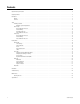
Contents Important Safety Instructions . . . . . . . . . . . . . . . . . . . . . . . . . . . . . . . . . . . . . . . . . . . . . . . . . . . . . . . . . . . . . . . . . . . . . . . . . . . . . . . . . . . . . . . . . . . . 4 Regulatory Notices . . . . . . . . . . . . . . . . . . . . . . . . . . . . . . . . . . . . . . . . . . . . . . . . . . . . . . . . . . . . . . . . . . . . . . . . . . . . . . . . . . . . . . . . . . . . . . . . . . . . 5 Description. . . . . . . . . . . . . . . . . . . . . . . . . . . .
List of Illustrations 1 2 3 4 5 6 7 8 9 10 11 Exploded View of TI2500 Series Thermal Imager . . . . . . . . . . . . . . . . . . . . . . . . . . . . . . . . . . . . . . . . . . . . . . . . . . . . . . . . . . . . . . . . . . . . . . . . 7 TI2535 and TI2550 Series Resource Disc GUI . . . . . . . . . . . . . . . . . . . . . . . . . . . . . . . . . . . . . . . . . . . . . . . . . . . . . . . . . . . . . . . . . . . . . . . . . . . 8 Removing Screws from Front of Enclosure. . . . . . . . . . . . . . . . . . . .
Important Safety Instructions 1. Read these instructions. 2. Keep these instructions. 3. Heed all warnings. 4. Follow all instructions. 5. Do not block any ventilation openings. Install in accordance with the manufacturer’s instructions. 6. Do not install near any heat sources such as radiators, heat registers, stoves, or other apparatus (including amplifiers) that produce heat. 7. Only use attachments/accessories specified by the manufacturer. 8.
Regulatory Notices This device complies with Part 15 of the FCC Rules. Operation is subject to the following two conditions: (1) this device may not cause harmful interference, and (2) this device must accept any interference received, including interference that may cause undesired operation. RADIO AND TELEVISION INTERFERENCE This equipment has been tested and found to comply with the limits of a Class A digital device, pursuant to Part 15 of the FCC rules.
Description The TI2500 Series combines a powerful advanced thermal imaging device in a compact fixed-mount environmental enclosure. The TI2500 Series cameras support serial communication for control of camera focus and other features. The serial protocol is user-configurable using a DIP switch on the camera assembly. Also, the cameras are preconfigured to support either RS-232 or RS-422 protocols.
Setup Before configuring the camera settings or installing the unit, you must remove the camera assembly from the enclosure to set up the basic wiring configurations (refer to Bench Setup on page 9). The camera can either be configured on a bench using a PC in a lab environment, or using a laptop in the field. The setup instructions vary slightly depending upon the type of configuration you choose. WARNINGS: • During setup, keep the lens cover on the camera to avoid scratching the lens.
INSTALLING SOFTWARE MINIMUM SYSTEM REQUIREMENTS • PC (Pentium® Pro processor, 166 MHz) with Windows® NT 4 (or later, not including Windows Vista®) • RAM: 128 Mbyte • Hard drive: 10 GB • Screen resolution: 800 x 600 pixels or higher • Serial communication port To install the TI25 GUI configuration software: 1. Insert the Pelco TI2535 and TI2550 Series resource disc (supplied) into the CD drive of the PC you will be using to configure the camera.
BENCH SETUP DISASSEMBLE THE ENCLOSURE 1. Use the supplied 1/8-inch hex wrench to loosen the two captive hex screws on the enclosure’s back plate. WARNING: Do not pull the “T” handle too aggressively during disassembly; doing so can damage cable connections. 2. Pull the “T” handle on the enclosure’s back plate to remove the enclosure sled. 3. Disconnect the ground cable from the ground stud on the inside of the enclosure’s back plate. 4.
CONNECT WIRING 1. Pull the shielded power cable through the gland on the left side of the enclosure’s back plate. NOTES: • • To prevent the entrance of dust or water, proper cabling (not supplied) must be used when wiring the enclosure. Use of flat cable or multiple cables will prevent the proper seal of the liquid-tight gland connectors. Pelco recommends the use of shielded power and serial cables.
4. Connect the input power wiring for either 24 VDC or 24 VAC to the screw terminals for pins 6 and 7 on the detachable connector (refer to Figure 5). Figure 5. Wiring to the Detachable Connector ì RS-422: TXRS-232: Transmit Data î RS-422: TX+ RS-232: Not Used ï RS-422: RX+ RS-232: Receive Data ñ RS-422: RXRS-232: Not Used ó r s Signal Ground Power DC- or AC High Power DC+ or AC Low 5.
INTERFACING WITH A PC 1. Attach the end of the serial cable that is not connected to the camera’s detachable connector to your PC’s serial port. 2. Proceed to Configuration on page 15; follow all steps in the Configuration section before completing the bench setup using the remaining steps in this section. 3. After completing the camera configuration, remove the serial cable from the detachable connector. REASSEMBLE THE ENCLOSURE 1. Place the supplied desiccant bag at the back of the enclosure. 2.
FIELD SETUP DISASSEMBLE THE ENCLOSURE 1. Use the supplied 1/8-inch hex wrench to loosen the two captive hex screws on the enclosure’s back plate. WARNING: Do not pull the “T” handle too aggressively during disassembly; doing so can damage cable connections. 2. Pull the “T” handle on the enclosure’s back plate to remove the enclosure sled. 3. Disconnect the ground cable from the ground stud on the inside of the enclosure’s back plate. 4.
REASSEMBLE THE ENCLOSURE 1. Place the supplied desiccant bag at the back of the enclosure. 2. Make sure that the lubricated O-rings on the front and rear covers of the enclosure are free of dirt and debris. WARNING: The O-rings must be lubricated prior to reassembling the enclosure. If needed, apply additional silicone lubricant (supplied) to the O-rings. 3. Reinstall the camera assembly. a.
Configuration The camera setup must be complete before the camera can be configured (refer to Setup on page 7). To open the TI25 GUI configuration software, on your PC go to Start >Programs>Pelco>TI25 GUI. CAMERA TAB SAVE SETTINGS After changing camera settings on any of the GUI tabs, click the Save Settings button to store the current sections as the new default settings. The next time that the camera power is cycled, these saved settings will remain as the defaults.
Perform Manual FFC Occasionally, image quality may degrade. When this happens, perform a manual FFC. After manually performing this process, the camera restarts the frequency clock and resets the baseline temperature. To manually perform the FFC: 1. Click the Camera tab. 2. Click the Manual button in the Flat Field Correction pane. 3. Click the Do FCC button. A FFC is performed.
VIDEO TAB CHANGING THE IMAGE ORIENTATION MODE Image orientation allows you to correct the video in the event that the camera is mounted inversely (in a ceiling mounted installation, for example). To change the image orientation: 1. Click the Video tab (refer to Figure 7). 2. Click the Invert button in the Image Orientation pane. The image appears inverted on the screen. 3. Once all required changes are made, click the Camera tab (refer to Figure 6 on page 15), and then click Save Settings.
CHANGING THE POLARITY/LUT SETTING The Polarity/LUT setting programs the specific palette of colors to represent the temperatures in the thermal image. These colors are not calibrated to a specific temperature. Rather, they represent the temperature variations within the thermal image. The following table lists the available display types and their color palettes. These palettes show the range of colors from hot temperatures to cold temperatures. Table B.
Pan When the “Zoom 2x” check box is selected, you can move the zoomed array region within the full-array area; this digitally simulates panning and tilting. Panning and tilting are defined as moving the camera image in the horizontal and vertical axes, respectively. There are two methods to pan and tilt using the GUI: adjust the vertical and horizontal sliders to move the zoomed array region or enter absolute offsets from the center to shift the zoomed array region.
AGC TAB The default settings on the automatic gain control (AGC) tab offer the best image quality for most scenes. You can make AGC adjustments to configure the camera to produce no image or an all black image. Restoring the factory defaults will return the camera to its factory default settings and likely restore normal camera operation (refer to Factory Defaults on page 15).
LINEAR PARAMETERS The linear parameters are made available depending on the mode selected. The following settings are available for Linear Parameters: • Contrast: Use the Contrast setting to adjust the contrast across the color palette. – Increase the Contrast setting to represent midrange temperatures closer to the extremes. – Decrease the Contrast setting to represent extreme temperatures closer to the midrange. • Brightness: The Brightness setting is only available when the AGC Mode is set to Manual.
ABOUT TAB Click the About tab (refer to Figure 9) to access basic camera information. If the camera is connected to the PC correctly, the following camera information appears: • Serial number • Part number • Software version • Firmware version This information needs to be provided when contacting Pelco Product Support. Figure 9.
Installation The TI2500 Series fixed-mount thermal imager can be mounted using an appropriate wall, ceiling, or pedestal mount (refer to the product specification sheet for a list of compatible mounts). For proper installation, refer to the instructions supplied with the mount. The enclosure should be attached to the mount by a minimum of two 1/4-20 fasteners (not supplied). WARNINGS: • Do not install the thermal imager without the sun shield; doing so will void the product’s warranty.
Troubleshooting NOTE: The system contains no user-serviceable parts. If there is a problem with your system, it must be returned to Pelco for servicing. Symptom: Degrading video quality Occasionally, image quality may degrade. 1. Perform a manual FFC. After manually performing this process, the camera restarts the frequency clock and resets the baseline temperature (refer to Flat Field Correction on page 15). 2. If the problem persists, perform the troubleshooting steps in Symptom: No video or poor video.
Maintenance CLEANING THE LENS 1. Saturate a piece of optical-grade tissue with deionized water and drape it over the lens. 2. Let the surface tension of the water pull the tissue onto the surface of the lens, and then drag the tissue across the lens. 3. Repeat this procedure several times, using a new piece of tissue each time. 4. Saturate a piece of optical-grade tissue with isopropyl alcohol. 5. Repeat step 2. 6.
Specifications Electrical Input Power 4 W, 6.2 VA nominal Input Voltage 18–27 VAC; 14–32 VDC Power Requirements 4W Heater 24 VAC, dual elements, thermostatically controlled Heater operates as a defogger; activates ON at 70°F (21°C), OFF at 85°F (29°C) Heater operates as a defroster; activates ON at 40°F (4°C), OFF at 67°F (19°C) Mechanical Construction Aluminum Finish Gray polyester powder coat Unit Weight 5.0 lb (2.
PRODUCT WARRANTY AND RETURN INFORMATION WARRANTY Pelco will repair or replace, without charge, any merchandise proved defective in material or workmanship for a period of one year after the date of shipment. Exceptions to this warranty are as noted below: • Five years on fiber optic products and TW3000 Series unshielded twisted pair (UTP) transmission products. • Three years on Spectra® IV products. • Three years on Genex® Series products (multiplexers, server, and keyboard).
Worldwide Headquarters 3500 Pelco Way Clovis, California 93612 USA USA & Canada Tel: (800) 289-9100 Fax: (800) 289-9150 International Tel: +1 (559) 292-1981 Fax: +1 (559) 348-1120 www.pelco.