® 00972 BK57 Blower, HK57 Heater, O/I-PCB and WD57 Defroster Kits for EH5700/EH5700L Series Environmental Enclosures Installation/ Operation Manual C1423M-D (10/03) Pelco • 3500 Pelco Way • Clovis, CA 93612-5699 USA • www.pelco.
CONTENTS Section Page 1.0 GENERAL .................................................................................................. 3 1.1 IMPORTANT SAFEGUARDS AND WARNINGS ............................... 3 2.0 DESCRIPTION .......................................................................................... 4 2.1 CERTIFICATIONS ............................................................................. 4 3.0 BLOWER KIT INSTALLATION ...................................................................
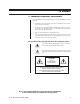
1.0 GENERAL 1.1 IMPORTANT SAFEGUARDS AND WARNINGS Prior to installation and use of this product, the following WARNINGS should be observed. 1. Installation and servicing should only be done by qualified service personnel and conform to all local codes. 2. Unless the unit is specifically marked as a NEMA Type 3, 3R, 3S, 4, 4X, 6, or 6P enclosure, it is designed for indoor use only and it must not be installed where exposed to rain and moisture. 3. Only use replacement parts recommended by Pelco. 4.
2.
3.0 BLOWER KIT INSTALLATION This section provides instructions for installing the BK57-1. BK57-2. and BK57-3 blower kits. For the following instructions, refer to Figure 1. Table B lists the parts shown in Figure 1. 1. Turn off power to the enclosure. 2. Unlatch and raise the enclosure lid. The gas spring will hold the lid in place when it is fully opened. NOTE: If you are using your enclo- 3. Remove the camera and sled. sure in a marine or high-moisture environment, skip steps 4-7.
Table A. 24 VAC Wiring Distances The following are the recommended maximum distances for 24 VAC applications and are calculated with a 10-percent voltage drop. (Ten percent is generally the maximum allowable voltage drop for AC-powered devices.) EXAMPLE: An enclosure that re- Wire Gauge 20 NOTE: Distances are calculated in Total vA consumed feet; values in parentheses are meters.
11. Thermostatically Controlled Operation Only (O/I-PCB Installed) - If the circuit board for thermostatic control of the fan already is installed, complete the installation as follows: a. Remove the plastic power supply barrier cover from the circuit board. b. Connect the plug from the fan into the FAN socket on the circuit board. c. Replace the plastic power supply barrier cover. d. Reinstall the camera and sled. e. Close the enclosure lid. f.
B 11 12 C 9 E 10 B C A B B A C J TO FAN 3 K RED 22 GA. (1 FT.) B BLACK 22 GA. (1 FT.) TO CIRCUIT BOARD 2 00968 1 Figure 1. Exploded Assembly Diagram for Blower Table B.
4.0 HEATER KIT INSTALLATION This section provides instructions for installing the HK57-1, HK57-2, and HK57-3 heater kits. For the following instructions, refer to Figure 2. Table C lists the pans shown in Figure 2. 1. Turn off power to the enclosure. 2. Unlatch and raise the enclosure lid. The gas spring will hold the lid in place when it is fully opened. 3. Remove the camera and sled. 4. Install the heater assembly in the front of the enclosure with the hardware that is supplied: 5. 6.
00965 Figure 2. Exploded Assembly Diagram for Heaters Table C. Exploded Assembly Parts List for Heaters Item Qty 1 2 1 2 2 2 1 Bracket/Heat sink Heater, 230 VAC Heater, 24 VAC Heater, 120 VAC Connector 57004020COMP HTR40220 HTR20024 HTR50120 CON1-480424-0 2 4 4 Spacer, .500" Length Internal Tooth Lock Washer, #4 Screw 4-40 x 1/4", Pan Head, Phillips Not Used Screw, 6-32 x 1/4", Pan Head, Phillips Internal Star Washer, #6 SPA8423 ZH4LWSIS ZH4-40X.
5.0 DEFROSTER KIT INSTALLATION This section provides instructions for installing the WD57-1, WD57-2, and WD57-3 defroster kits. For the following instructions, refer to Figure 3. Table D lists the parts shown in Figure 3. NOTE: Window defrosters manufac- 1. Turn off power to the enclosure. 2. Unlatch and raise the enclosure lid. The gas spring will hold the lid in Place when it is fully opened. 3. Remove the camera and sled. 4.
1 2 TO CIRCUIT BOARD 00969 Figure 3. Exploded Assembly Diagram for Defroster Table D.
6.0 CIRCUIT BOARD KIT INSTALLATION This section provides instructions for installing the O/I-PCB circuit board kit. For the following instructions, refer to Figure 4. Table E lists the parts shown in Figure 4. 1. Install the circuit board kit (O/I-PCB): a. Remove the mounting bracket from the circuit board. It is not required. b. Install two 4-40 x 1/4-inch screws, washers, and grounding clips (items B, C, and D) in the circuit board.
00966 Figure 4. Exploded Assembly Diagram for Circuit Board Table E. Exploded Assembly Parts List for Circuit Board Item 14 1 2 3 4 5 6 7 A B C D Qty Description Part Number 1 2 1 1 Not Used Not Used Not Used Power Supply Barrier Cover Power Supply Barrier Circuit Board Circuit Board Insulator EH470010019 EH47004029COMP PCB9000276ASSY EH450010256 2 2 2 Not Used Internal Tooth Lock Washer, #4 Screw 4-40 x 1/4", Pan Head. Phillips Grounding Clip ZH4LWSIS ZH4-40X.
WARNING: Camera damage possible. You 8. Refer to Figure 5 and connect the camera’s power input to the circuit board. When the power requirements are the same, there are two ways to connect power: can damage your camera if you connect it to the wrong connector. (1) If your camera will use the same power as the enclosure, plug the camera into the CAM 1 socket on the circuit board inside the enclosure. A three-pin plug is supplied as loose equipment.
00967 Figure 5.
7.
00970 Figure 6.
Figure 7. Circuit Board Component Locations 00971 Figure 8.
9.0 WARRANTY AND RETURN INFORMATION WARRANTY Pelco will repair or replace, without charge, any merchandise proved defective in material or workmanship for a period of one year after the date of shipment. Exceptions to this warranty are as noted below: • Five years on FT/FR8000 Series fiber optic products. • Three years on Genex® Series products (multiplexers, server, and keyboard).