MS500 Series Manual Switchers Installation/ Operation Manual C820M-D (1/01) Pelco • 3500 Pelco Way, Clovis • CA 93612-5699 USA • www.pelco.
CONTENTS Section Page IMPORTANT SAFEGUARDS AND WARNINGS ................................................................ 3 DESCRIPTION ................................................................................................................... 4 MODELS .................................................................................................................... 4 INSTALLATION ..................................................................................................................
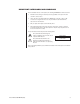
IMPORTANT SAFEGUARDS AND WARNINGS Prior to installation and use of this product, the following WARNINGS should be observed. 1. Installation and servicing should only be done by qualified service personnel and conform to all local codes. 2. Unless the unit is specifically marked as a NEMA Type 3, 3R, 3S, 4, 4X ,6 or 6P enclosure, it is designed for indoor use only and it must not be installed where exposed to rain and moisture. 3. Only use replacement parts recommended by Pelco. 4.
DESCRIPTION The MS500 Series provides an inexpensive and reliable method of switching 4 to 18 inputs to a single monitor output using interlocked manual pushbuttons. Included in this series is the MS540 switcher with two monitor outputs and the capacity to switch up to 40 inputs with a 14 pushbutton panel. The MS500 Series Switchers are designed for either looping or terminating operation, depending on the model.
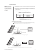
INSTALLATION NOTE: For the maximum recommended cable distances refer to the installation manuals supplied with equipment (camera, lens and monitor) to be used with the switcher. 1. Place the unit on a flat surface, or install it in an equipment rack using the appropriate rack-mount kit. 2. Refer to Figures 1 - 6 and select the desired configuration for your installation. Make all equipment connections as illustrated in the drawings. Refer to Table A for the type of coaxial cable to use. 3.
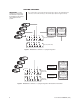
LOOPING SWITCHERS IMPORTANT: Looping Use coaxial cable to connect the input and looping video cables to the appropriate input connectors. Connect the monitor(s) to the monitor output. (Refer to Figures 3 and 4.) switchers do not have internal termination. Inputs must be terminated at 75 ohms by other equipment in the system.
SWITCHERS WITH AUDIO FOLLOW NOTE: Configuration does MS500 Series models with “AF” in the suffix have a connection for an audio signal source. Using appropriate cable with compatible connectors, connect audio signal sources to RCA jack (refer to Figure 5). not permit two-way communication. Microphones or speakers, etc., can be installed at the camera site. TERMINATE MONITOR (SWITCH IN THE 75Ω POSITION) AUDIO IN/OUT CAMERA AUDIO IN/OUT 4 3 2 1 MON VIDEO OUT MS504AF (REAR VIEW) Figure 5.
SWITCHERS WITH AMPLIFIED OUTPUT The MS540DT and MS540LDT switchers provide both an amplified output (Monitor 1) and a non-amplified output (Monitor 2). Most installations require the use of Monitor 2 output for proper operations. NOTE: Use Monitor 2 non-amplified output only when interfacing with the MPT9000CZ/MPT9000PZ or KBD9000/KBD9000-X Coaxitron controls. OPERATION To operate the MS500 Series Switcher, plug in the power cord and press a camera button to view video from the corresponding camera.
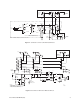
AUDIO FOLLOW OPTION CON 3505 RCA JAX AUDIO OUTPUT AUDIO INPUTS T1 1 18 V.A.C. BLK BLK I1 I2 IN R2 75Ω R2 75Ω RN 75Ω RED F1 BLK/YEL GRN GRN/YEL 1/16 AMP AC INPUT N 2 1 YEL BLK/GRN GRY BLK/RED BRN -FOR 220 VAC INPUT ADD JUMPER TO 2 & 3 REMOVE JUMPER FROM 1 & 3, 2 & 4 2 1 VIDEO INPUTS DELETE TERMINATION RESISITORS 75 OHM FOR LOOPING TYPICAL CONNECTION FOR LOOPING N VIDEO OUTPUT Figure 7. Schematic for 4-18 Position Manual Switchers 75 TYP.
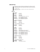
SPECIFICATIONS VIDEO Inputs: 4, 8, 12, or 40 as indicated by the last two digits of the model number.
GENERAL Switching: Interlocked manual pushbuttons Construction: Cover Chassis Panel Steel, black polyester powder coat Steel, zinc plated Aluminum, black polyester powder coat Environment: 32° to 120°F (0° to 48.89°C) Dimensions MS504 Series (except AFL, BAF, and BAF models): MS504AFL, MS504BAF, MS504BAFL, and MS508 Series (except AFL model): MS508AFL, MS512 Series, MS518 Series, and MS540DT (except MS518AFL and MS540LDT): MS518AFL and MS540LDT: 1.75 (H) x 5.3 (W) x 9.3 (L) inches (4.45 cm x 13.
PRODUCT WARRANTY AND RETURN INFORMATION WARRANTY Pelco will repair or replace, without charge, any merchandise proved defective in material or workmanship for a period of one year after the date of shipment. Exceptions to this warranty are as noted below: • Five years on FT/FR8000 Series fiber optic products. • Three years on Genex ® Series products (multiplexers, server, and keyboard).