
user manual

C2652M (1/08) 11
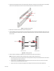
2. Mount one front-mount support rail with one rear-mount support rail back-to-back, and attach the rails using three 8-32 x 0.375-inch Phillips
truss head screws (refer to Figure 9). Leave the screws loose until the support rails are attached to the rack in step 7.
Figure 9. Assembling a Support Rail
3. Repeat step 2 for the other set of front-mount and rear-mount support rails.
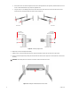
4. If you are installing the unit into a square-hold rack, continue with this step; otherwise, skip this step and proceed to step 5. Insert 10 cage
nuts into the square-hole rack (refer to Figure 10). Align the top and bottom cage nuts on the front racks with the top and bottom cage nuts
on the rear racks.
Figure 10. Inserting Cage Nuts
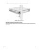
5. Attach one support rail assembly to the equipment rack in the desired location as follows (refer to Figure 11):
NOTE: The support rail assemblies are identical and may be used on either the right or left side of the rack.
a. Position the ear of the front-mount rail against the front of the equipment rack, and align the top and bottom holes in the ear of the rail
with the threaded holes (or cage nuts) in the rack.
b. Using two 10-32 x 0.5-inch Phillips flat head screws, attach the ear of the rail to the front of the rack. Insert the screws from the
outside of the rack, pointing toward the back of the rack.
c. Adjust the rails to the correct depth of the equipment rack by sliding the rear-mount rail to the back of the equipment rack.
(3) SCREWS, 8-32 X 0.3
75
PHILLIPS TRUSS HEAD
CAGE NUT
REAR-MOUNT RAIL
FRONT-MOUNT RAIL
CAGE NUT
ALIGN
ALIGN