® Installation/Operation KBD300A Universal Keyboard C527M-L (3/04) Pelco • 3500 Pelco Way • Clovis, CA 93612-5699 USA • www.pelco.
[2] Pelco Manual C527M-L (3/04)
CONTENTS Section Page IMPORTANT SAFETY INSTRUCTIONS ........................................................................................................... 5 REGULATORY NOTICES .................................................................................................................................. 6 DESCRIPTION ................................................................................................................................................. 7 INSTALLATION – CM6700 MODE .........
List of Illustrations Figure Page 1 Wiring Diagram for Local/Remote Keyboards ................................................................................... 10 2 Keyboard Cabling Diagram ................................................................................................................. 10 3 Data Cables Plugged into COM 5 and 6 (CM6800-48X8 Shown) ...................................................... 12 4 Connecting Remote Keyboards (CM6800-48X8 Shown) ....................................
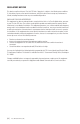
IMPORTANT SAFETY INSTRUCTIONS Read these instructions. Keep these instructions. Heed all warnings. Follow all instructions. Do not use this apparatus near water. Clean only with dry cloth. Do not block any ventilation openings. Install in accordance with the manufacturer’s instructions. Do not install near any heat sources such as radiators, heat registers, stoves, or other apparatus (including amplifiers) that produce heat. Only use attachments/accessories specified by the manufacturer.
REGULATORY NOTICES This device complies with part 15 of the FCC Rules. Operation is subject to the following two conditions: (1) this device may not cause harmful interference, and (2) this device must accept any interference received, including interference that may cause undesired operation. RADIO AND TELEVISION INTERFERENCE This equipment has been tested and found to comply with the limits of a Class B digital device, pursuant to part 15 of the FCC rules.
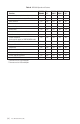
DESCRIPTION The KBD300A Universal Keyboard has many operational features (refer to Table A) and can be used in numerous operational modes: CM6700 Mode: Program and operate the CM6700 Matrix Switcher/Controller Unit (SCU). Also control a Genex® multiplexer from a CM6700. Multiple keyboards can be used in this mode. CM6800 Mode: Program and operate the CM6800 Matrix Switcher/Controller Unit (SCU). Also control a Genex multiplexer from a CM6800 SCU. Multiple keyboards can be used in this mode.
Table A.
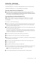
INSTALLATION – CM6700 MODE There are two keyboard ports on the CM6700 SCU. The LOCAL KEYBOARD port is for connecting a single keyboard within a distance of 25 feet (7.6 meters). The REMOTE KEYBOARD(S) port is for connecting additional remote keyboards. Connecting a Keyboard to the Local Keyboard Port Use the data cable that is supplied with the keyboard.
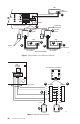
KBD LOCAL KEYBOARD LOCAL KEYBO ARD 1 25-FOOT KEYBOARD DATA CABLE CM6700 USER-SUPPLIED CABLE ADDITIONAL KEYBOARDS REPLACE COVER 3 6 REPLACE COVER 6 KBD KBD 7 2 8 KBDKIT 2 7 8 SET SWITCHES 25-FOOT KEYBOARD 25-FOOT KEYBOARD DATA CABLE DATA CABLE REMOTE KEYBOARDS 01225 Figure 1.
INSTALLATION – CM6800 MODE You can connect up to eight KBD300A keyboards to any of the following ports: For the CM6800-48X8: COM 5 (one direct-powered keyboard or up to eight remotely connected keyboards) COM 6 (same as COM 5) COM 7 (up to eight remotely connected keyboards) COM 8 (same as COM 7) The total number of KBD300A Series keyboards connected to the CM680-48X8 cannot exceed 16.
MAXIMUM NUMBER OF KEYBOARDS POWERED BY COM 5 & 6: 1 PER PORT NOTE: THE TOTAL NUMBER OF KBD300A SERIES KEYBOARDS CONNECTED TO THE CM6800 CANNOT EXCEED 16. KBDKIT(-X) REQUIRED WHEN WIRING MORE THAN 1 KEYBOARD TO A PORT.
Connecting KBD300A Remote Keyboards For remote keyboard connections, use COM 5, 6, 7, or 8 for the CM6800-48X8 and COM 4 and 5 for the CM6800-32X6. Each port can support up to eight KBD300A keyboards. Do not exceed 16 total keyboards for the CM6800-48X8 and eight total keyboards for the CM6800-32X6. A KBDKIT or KBDKIT(-X) is required to connect remote keyboards. Each kit contains two RJ-45 wall blocks and a transformer. Use one wall block for each keyboard. Refer to Figure 4 (CM6800-48X8 shown).
MAXIMUM NUMBER OF KEYBOARDS: 8 PER PORT NOTE: THE TOTAL NUMBER OF KBD300A SERIES KEYBOARDS CONNECTED TO THE CM6800 CANNOT EXCEED 16.
INSTALLATION – CM6700 ASCII MODE One ASCII keyboard can be installed, using either an RS-232 or RS-422 interface. If additional local and remote keyboards are used, you should install them according to the instructions in the Installation – CM6700 Mode and Installation – CM6800 Mode sections before doing an ASCII installation.
Set the keyboard DIP switches for ASCII Mode according to the instructions in the Switch Settings section. Plug in the keyboard data cable. Plug the +12 VDC power supply into a suitable outlet. Plug the KBDKIT or KBDKIT-X transformer into a suitable outlet. Apply power to the CM6700 SCU (if not already powered). To initialize the keyboard, wait five seconds after power-up, enter the number for the monitor you are viewing (1-4), and press MON. The LED display shows the number entered.
RS-422 Interface (CM6700) Refer to Figure 6. Remove the cover from the CM6700 SCU and verify that the DIP switches for COM 2 are set for RS-422. Refer to the COM 2 Port section in the CM6700 Installation/Operation Manual for setting the switches. Reinstall the cover. Use an existing CM6700 keyboard to program the COM 2 communication port. (If there is no other keyboard, use the one you are installing. Set all DIP switches OFF and plug the keyboard into the Local Keyboard port on the back of the CM6700.
1 NOTE: A SEPARATE PATH MUST BE PROVIDED FOR VIDEO TO THE MONITOR. CM6700SCU LOCAL KEYBOARD KBDKIT RJ-45 WALL BLOCK TERMINALS 10 POWER UP SCU 2 4 5 3 6 2 7 1 8 6 REPLACE COVER 4 TERMINAL 1 KBD300A 2 MAXIMUM DISTANCE OF 4,000 FEET. USE SHIELDED TWISTED PAIRS SUCH AS BELDEN 9843 OR EQUIVALENT. 4 4 5 6 7 8 SCU COM 2 PIN 12 (RX+) 11 (RX-) 8 (TX-) 7 (TX+) TO WALL BLOCK TERMINAL 1 (TX+) 2 (TX-) 7 (RX-) 8 (RX+) 12 VAC 9 Figure 6.
INSTALLATION – CM6800 ASCII MODE RS-232 Interface (CM6800) An RS-232/RS-422 converter and power supply (Pelco part number PV130) are required. They are not included and must be ordered separately. Refer to Figures 7 (CM6800-48X8 shown) and 9. Use an existing CM6800 keyboard to program the COM 1, 2, 7, or 8 communication port for the CM6800-48X8 or COM 1 or 2 communication port for the CM6800-32X6. (If there is no other keyboard, use the one you are installing.
Apply power to the CM6800 (if not already powered). To initialize the keyboard, wait five seconds after power-up, enter the number for the monitor you are viewing, and press MON. The LED display shows the number entered. You can now use the keyboard to perform all normal keyboard functions, except you cannot program the CM6800. Go to the Programming and Operation section and program and test for proper operation.
RS-485 Interface (CM6800) Refer to Figures 8 (CM6800-48X8 shown) and 9. Use an existing CM6800 keyboard to program the COM 4, 7, or 8 communication port (CM6800-48X8) or COM 4 communications port (CM6800-32X6). (If there is no other keyboard, use the one you are installing. Set all DIP switches OFF and plug the keyboard into the Local Keyboard port on the back of the CM6800. Remove when programming is complete.) Do the following to program the COM port: a. Press the PGM key.
PELCO SWITCHER MODEL CM6800 MAIN MENU 1 2 3 4 5 6 7 8 9 10 11 12 13 14 SET SERIAL PORT 05 CAMERA LOGICAL CAMERA MONITOR ACCESS TIME & DATE PORT PRIORITY SEQUENCE MACRO ALARM CONTACTS EVENT TIMER SET AUXILIARY MENU SET PASSWORD ABOUT CM6800 DEVICE: TYPE: BAUD RATE: PARITY: DATA BITS: STOP BITS: ASCII RS485 9600 ODD 8 1 1 CM6800 RETURN ENGLISH AL AR M 1 2 3 4 5 6 7 8 COM RETURN 10 16 1 5 POWER UP SCU C O NTR O L 2 2 6 3 7 4 8 P TZ A T + COM 4, 7, OR 8 31 32 3 4 7 8 T - R R +
COM PORTS 7, 8 RS-485 (PROGRAMMABLE TO RS-232) PIN 1 PIN 8 RS-485 FUNCTION 1-----Rx+ 2-----Rx3 -----NC 4 -----NC 5-----GROUND 6-----NC 7-----Tx8-----Tx+ RS-232 FUNCTION 1-----Rx 2 -----NC 3 -----NC 4 -----NC 5-----GROUND 6-----NC 7-----NC 8-----Tx COM PORTS 1, 2 RS-232 COM PORT 3 M, RS-485 COM PORT 4 RS-485 COM PORTS 5, 6 RS-485 PIN 1 PIN 1 PIN 1 PIN 1 PIN 8 PIN 8 PIN 8 PIN 8 1-----Rx 2-----NC 3-----NC 4 -----NC 5-----GROUND 6 -----NC 7 -----NC 8-----Tx 1-----MRx+ 2-----MRx3 -----NC 4 -----
INSTALLATION – DIRECT MODE The keyboard is wired directly to a maximum of 16 receivers. You can communicate using Pelco P Protocol or Pelco D Protocol. Direct Mode installation/operation is not the same as CM6700 Mode or CM6800 Mode installation/operation. A separate system, such as an MS500 or VA6100 switcher, is required for routing video to the monitor(s). In Direct P and Direct D modes you can now change the zoom speed of a PTZ by entering a number from 1 to 4 followed by a zoom command.
CONFIGURE RECEIVERS TO RECEIVER(S) RX-/RX+ TWISTED PAIR KBD300A 4 5 3 6 TX- 2 7 TX+ 1 8 6 6 REPLACE COVER 12 VA C SET SWITCHES 9 KBDKIT OR KBDKIT-X 25-FOOT KEYBOARD DATA CABLE 20110 Figure 10.
SWITCH SETTINGS To set the switches on the keyboard (refer to Figure 11): Remove the two screws and the DIP switch cover plate from the rear of the keyboard. Set the switches: • Address (Switches 1-4) Position the switches according to Table B. Each keyboard in the system must have a different address, including the local keyboard. To make programming easier, address keyboards in ascending order. NOTE: CM6700 accepts only eight addresses. Table B.
Replace the cover plate. PIN 1 1 ON 3 2 1 2 3 4 5 6 7 8 KBD300 RJ-45 JACK PINOUTS 1 3 1 TX+ 2 TX– 3 12 VAC/DC 4 NONPOLAR } 5 GND 6 7 RX– 8 RX+ DOWN = ON 01227 Figure 11. Keyboard Rear Panel PROGRAMMING AND OPERATION Table D. Keyboard Functions Circled numbers refer to Figure 13. Function Procedure Select Monitor* LED display shows monitor number in run mode. Enter monitor number and press MON to select. Select Camera Enter camera number (1-16) and press CAM to select.
Table D. Keyboard Functions (continued) Function Procedure Patterns Programming and operation varies with the receiver type. Spectra® domes (before version 3.0) can use one long (1 minute) or two short (0.5 minute) patterns. Spectra domes (version 3.0), Spectra II™ domes and Esprit® Integrated Positioning Systems can use one long (1.5, 3 or 6 minutes) or two short (0.75, 1.5 or 3 minutes) patterns. (Select pattern lengths at the positioning system’s menu.
Table D. Keyboard Functions (continued) Function Auxiliaries/ Relays Procedure For the CM6700: F1 – F3 control only the auxiliaries built into the CM6700 SCU. These outputs can be programmed for momentary, keyed, latched, or alarm operation. Refer to the CM6700 manual for programming instructions. F1/LATCH: Activate/deactivate auxiliary 1 relay.* F2/OFF: Activate/deactivate switcher auxiliary 2 TTL output.* F3/MOM: Activate/deactivate switcher auxiliary 3 TTL output.
2 1 3 4A 4B 4C 5 6 7 17 8 16 9 15 10 14 12 13 11 Figure 12. Keyboard Functions Table E. KBD300A Button Functions Reference Number 1 2 3 4A-C 5 6 7 8 9 10 11 12 13 14 15 16 17 [ 30 ] Pelco Manual C527M-L (3/04) Description LED display Shift key Shift key LED Sequence keys: Previous, Next, Hold Function keys F1/Latch, F2/Off, F3/Mom control auxiliaries. With Shift on they control multiplexer display. The AUX ON and AUX OFF keys control receiver auxiliaries.
Scanning Functions Operation of the scanning functions depends on the kind of receiver or pan/tilt mechanism you have and the operating mode of your keyboard (CM6700, CM6800, or Direct Mode). There are four types of scanning functions: auto (moves camera back and forth between stops), random (moves camera in a random pattern), frame (moves camera back and forth in 10 degree steps), and preset (sequences camera through all programmed presets, pausing between each). Operate scans according to Table F.
Programming Limit Stops Spectra and Esprit can be programmed for scan and manual limit stops. Program left limit before programming right limit. Locate camera at desired limit. Enter the set code from Table G. Hold the PRESET key for two seconds. In CM6700 and CM6800 modes, a label appears on the monitor. Use F1 and F2 to edit the label, then select SET and press ACK or tap the joystick to the right and release. To cancel all limit stops, enter 95. Hold the preset key for two seconds.
Zones The Zone function is available on Esprit and Spectra positioning systems when operated through a CM6700 or CM6800 switch.* This function puts a label on the screen to identify the viewing area. Zones can also be blanked to prevent viewing while the camera is positioned in the zone. Up to eight pan (horizontal) zones can be defined (zones are not affected by tilt or zoom). Higher numbered zones take precedence so that if zones overlap, the one with the higher number is in effect.
SPECIFICATIONS GENERAL Keyboard Keypad: Electromechanical Joystick: 3-axis, vector-solving, with twisting, return-to-center head Digital Display: Red LED, 7-segment, 2 cells Shift Mode Indicator: Green LED Ambient Operating Temperature: 20° to 120°F (-7° to 49°C) Humidity: 10–90% non-condensing Dimensions: 9.50 (W) x 7.125 (D) x 2.25 (H) inches (24.13 x 18.1 x 5.72 cm) Weight: 2.5 lb (1.
CM6800 ASCII Mode Interface: RS-485 Protocol: Pelco ASCII Baud: 9600 Communication Parameters: 8 data bits, 1 stop bit, odd parity Direct P Mode Interface: Protocol: Baud: Communication Parameters: Direct D Mode Interface: Protocol: Baud: Communication Parameters: RS-485 Pelco P 4800 8 data bits, 1 stop bit, no parity RS-485 Pelco D 2400 8 data bits, 1 stop bit, no parity (Design and product specifications subject to change without notice.
[ 36 ] Pelco Manual C527M-L (3/04)
REVISION HISTORY Manual # Date Comments C527M 11/97 Original version. C527M-A 1/98 Revised manual to include Direct Mode Installation/Operation instructions. Added CM6700 Operations instructions. C527M-B 4/98 Revised installation instructions as a result of hardware changes to the rear panel of the CM6700 SCU. 6/98 Added Section 1.2, Regulatory Notices, and Section 1.3, Certifications. C527M-C 9/98 Revised manual to show new DIP switch and switch settings.
PRODUCT WARRANTY AND RETURN INFORMATION WARRANTY Pelco will repair or replace, without charge, any merchandise proved defective in material or workmanship for a period of one year after the date of shipment. Exceptions to this warranty are as noted below: • Five years on FT/FR8000 Series fiber optic products. • Three years on Genex® Series products (multiplexers, server, and keyboard).
® World Headquarters 3500 Pelco Way Clovis, California 93612 USA USA & Canada Tel: 800/289-9100 Fax: 800/289-9150 International Tel: 1-559/292-1981 Fax: 1-559/348-1120 www.pelco.