
Operation Manual

15
14
TECHNICAL SPECIFICATIONS
BUILDING-IN
Building-in
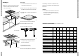
1. Make the cut-out in the work surface. Ensure
that there is sufficient space allowed at the
sides and at the back.
Please note:
■ The distance between the hob and the rear
wall must be at least 40 mm.
2. Make a hole in the side of the kitchen cabinet
to enable the gas pipe to be passed through.
3. Stick the strips of sealant to the underside of
the hob.
4. Screw the 4 clamps under the appliance.
5. Place the appliance in the cut-out.
6. Secure the appliance in position.
7. Make the gas connection. Check the gas
connections with a soap/water mixture
(see "Gas Connection").
8. Put the plug in the socket
(see "Electrical Connection").
9. Test to check the appliance is operational.
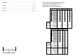
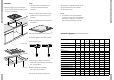
Technical specifications (also see table on cover)
Type of hob GKB255 GKV155 GKB255 GKV155 GKV101 GKV106 GKB285
Alu Alu Alu
Electric:
3-core connection lead ■■■■ ■■
Connection AC 230 V - 50Hz -
0,6 VA ■■■■ ■■
Spark ignition ■■■■ ■■
Gas:
Connection G3/8” ■■■■■■■
Dimensions (appliance):
600x45x530 wxhxd in mm ■
600x67x530 wxhxd in mm ■
640x45x530 wxhxd in mm ■
640x67x530 wxhxd in mm ■
580x67x510 wxhxd in mm ■■
830x55x530 wxhxd in mm ■
Dimensions (recess):
560x490 wxd in mm ■■■■■■
750x490 bxd in mm ■
The building in of the hob in combination with a
built-in oven is described in the installation guide
for the oven.
Attention!
■ The underside of this built-in hob becomes
hot. Take care that you do not place any
flammable or plastic objects in any drawer
under the appliance.
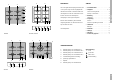
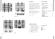
fig. 7
560 490
fig. 4 GKB 255/GKV
490
750
fig. 5 GKB 285
fig. 6