Owner’s Manual & Installation Guide Traditional Tubs Contemporary Tubs Tub Filler Faucets Note: Read all instructions before proceeding with installation. All specifications are subject to change without notice.
Traditional Tubs Highview – 54” Rolltop Tub Laughlin – 60” Rolltop Tub Brookdale – 60” Slipper Tub Glendale – 67” Slipper Tub Mendham – 60” Dual Tub on Plinth Dalton – 60” Dual Tub on Feet Eastchester – 72” Dual Tub on Plinth Northfield – 72” Dual Tub on Feet Contemporary Tubs Crestmont – 67” Contemporary Oval Tub on Plinth Newcastle – 67” Contemporary Apron Tub
Table of Contents: Warranty..............................................................................................................................2 Before you begin / Safety instructions.............................................................................3 Installation Overview.........................................................................................................4 Installing Feet / Tub Base..................................................................................
Warranty Pelham & White warrants, to the initial consumer purchaser, the surfaces of the bathtub and acrylic plinths to be free of defects in material and workmanship during normal residential use for a period of 25 years from the date of purchase. This warranty does not cover normal wear and tear or damage to the surface caused by the use of chemicals that break the structural bonds in the acrylic material (see cleaning & maintenance page).
Before you begin: • Observe all local plumbing/building codes and ensure flooring support is adequate. Installation of backflow prevention must comply with local codes and regulations. In certain states models with handshower must be installed with a listed inline anti-scald device. • Before you begin work, carefully uncrate and inspect the tub for any damage. If there is a problem, do not install the tub. Immediately report the problem to the dealer. • Ensure the floor will support 1200 lbs.
SUMMARY OF INSTALLATION PROCESS: Step 1 - PREPARE THE SITE NOTICE: Shut off hot and cold water. Make sure the floor will support 1200 lbs. Position the plumbing according to the roughing-in information. Cap the supplies and check for leaks. Make sure the drain location corresponds to the bath outlet. Step 2 - PREPARE THE TUB CAUTION: Risk of personal injury. Obtain sufficient help to carefully lift or move the tub. Level the bath as needed with adjusters on appropriate feet.
STEP 3 INSTALLING THE FEET/TUB BASE Your tub will mount in one of these ways: with feet - see page 6-7 with plinth - see page 8-9 with cradle - see page 10 5
INSTALLING CANNONBALL AND BALL & CLAW FEET 1. Ensure tub surface is protected during assembly, installation and the final phase of construction. 2. Place tub on floor, upside down, and attach feet to tub with fasteners provided. Do not overtighten. 3. Turn tub right side up, place in desired position and mark foot anchoring locations. 4. Carefully move tub and drill (4) 7/16" diameter holes in the floor to accommodate the foot anchors. 5.
INSTALLING RECTANGULAR FEET #2 Adjustable Disc #1 Threaded Stud #8 Chrome Plated Rectangular Feet #3 Bolt #4 Washer #5 Nut #6 Washer Floor #7 Mounting Bracket Drilled Anchor Hole Screw threaded stud up/down to desired height based on depth of the hole in the floor Turn adjustable disc up/down to level tub, as needed 1. Ensure tub surface is protected during assembly, installation and the final phase of construction. 2.
INSTALLING WOOD PLINTH #1 Adjustable Feet Threaded Tub Bolts #2 Mounting Nut #3 Washer 1. Ensure tub surface is protected during assembly, installation and the final phase of construction. 2. Place tub on floor, upside down, and place the wooden plinth on tub by aligning holes with tub bolts. 3. Secure the plinth by attaching #3 washers and #2 mounting nuts to the threaded tub bolts. Do not overtighten. 4. Turn the tub and plinth back over and set in desired location. 5.
INSTALLING ACRYLIC PLINTH #1 Adjustable Foot #6 Flat Metal Bracket #3 Nut Ø12 #4 Lock Washer #2 Nut Ø10 #5 Flat Washer Caulk Here & Here See Note 1. Ensure tub surface is protected during assembly, installation and the final phase of construction. 2. Place tub on floor, upside down, and place the acrylic plinth on tub by aligning holes with tub bolts. 3. Secure the plinth by attaching washers (#4 & #5) and mounting nuts (#3) to the threaded tub bolts in the order shown. Do not overtighten. 4.
INSTALLING CRADLE TOP RAIL CURVED NOTCHES End Assembly Side Rails 2. Mounting Bolt 5. Cylinder Nut 3. Suction Cup 1. Leveling Feet End Assembly 6. Wood Dowel Pins 4. Decorative Plug 1 Leveling Feet 4 Pcs 2 Mounting Bolt 8 Pcs 3 Suction Cup 4 Pcs 4 Decorative Plug 8 Pcs 5 Cylinder Nut 8 Pcs 6 Wood Dowel Pins 8 Pcs Side Rails connect the End Assemblies with the Side Rails using the Wooden Dowel Pins (#6) in the top holes. The 3.
STEP 4 INSTALLING THE DRAIN O-ring Coupling Nut Silicone Sealant Tailpiece Strainer Flange Gasket Drain Ell Trap Inlet FIGURE 1 Connect strainer to drain ell FIGURE 2 Connect tailpiece to trap inlet Tapered Rubber Gasket Overflow Plate Overflow Ell O-ring Tee Coupling Nut FIGURE 3 Assemble tee section FIGURE 4 Secure drain to tub with overflow plate 1. Connect Drain Strainer & Drain Ell. Use silicone sealant. DO NOT use plumbers putty to seal. 2. Insert tailpiece into trap inlet.
STEP 5 INSTALLING THE FAUCET There are two styles and three faucet mounting methods. Please refer to the appropriate page for your application.
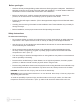
TRADITIONAL DECK MOUNT TUB FAUCET Notes: 1. Please ensure all local plumbing and building codes are observed when installing these faucets. 2. Water supply lines must be roughed in on 8” centers. T-FB1 Union Nut 17 T-DLBO 11 Washer (10) Step 2 9 T-HLVR 11 Attach T-DLBO deck elbows to union nuts on Seal Washe Rubber back of faucet body using one #10 rubber gasket on each elbow.
TRADITIONAL DECK MOUNT TUB FAUCET (cont.) 1 T-FB1 Union Nut 2 T-DLBO Cone Washer Flange (top of tube) Nut Step 5 U-FSUP Tub NOTE: U-FSUP SUPPLY LINES CAN BE CUT TO CORRECT HIEGHT. MAKE SURE TO CUT FROM BOTTOM OF TUBE. Attach #1 handshower holder with #2 rubber gasket to outlet above diverter handle.
Metal Washer LOCK NUT CONE WASHER Cone Washer CONE WASH TRADITIONAL DECK MOUNT OPTIONAL SHUT OFF VALVE NUT NUT White Porcelain Valve Stem OTE: U-FSUP SUPPLY LINES CAN NOTE: U-FSUP SUPPLY LINES CAN E CUT TO CORRECT HIEGHT. U-FSUP BE CUT TO CORRECT HIEGHT. MAKE SURE TO CUT FROM FROM T-HPLV T-HLVRMAKE SURE TO CUT OTTOM OF TUBE.U-DVLV BOTTOM OF TUBE. Handle Hub U-FSUP T-HCRS Step 1 Screw handle hubs onto valve stems. Disassemble handle and install onto stem by securing with screw included.
TRADITIONAL FLOOR MOUNT TUB FAUCET Notes: 1. Faucet is not for use on concrete floors. 2. Please ensure all local plumbing codes are observed during installation 3. Water supply lines must be roughed in on 8” centers. T-FB1 Union Nut 17 U-FRSR 11 Washer (10) 9 T-HLVR 11 Step 2 Rubber Seal Washer Attach hot and cold risers U-FRSR to union nuts on back of faucet body using one #10 rubber gasket on each riser.
T-FB1 TRADITIONAL FLOOR MOUNT TUB FAUCET (cont.) U-FRSR Side View End View U-SBRC Tub NOTE: When using the U-SBRC support brace it must be installed onto faucet risers prior to securing to floor 8" Step 6 Slide #25 decorative escutcheon onto bottom of risers U-FRSR and push part way up. Screw #26 floor flange onto threaded portion of each riser until it stops. Step 7 Insert risers into hole in floor and secure floor flanges with appropriate screws/bolts for your flooring type.
CONTEMPORARY FLOOR MOUNT TUB FAUCET Notes: 1. Faucet is not for use on concrete floors. 2. Please ensure all local plumbing codes are observed during installation 3. Water supply lines must be roughed in on 8” centers. C-HLVR 1 1 17 Screw 16 Spokes Union Nut 10 7 (Allen Wrench) Spokes C-FRSR 3 9 16 C-HCRS C-FB1 Step 1- Install #1 spout into Step 2- Screw #16 handle hub C-FRSR faucet body by pushing straight onto hot/cold cartridges #9 & #17. down.
CONTEMPORARY FLOOR MOUNT TUB FAUCET (cont.) Step 8- Slide #25 decorative escutcheon down to cover floor flange. Step 9- Tighten optional support bracket to risers and drain 8" FIGURE 5 Supply line spacing 16 30 Step 10- Attach small end of #18 handshower hose with #30 washer to outlet below diverter faucet handle. Step 11- Attach large end of #18 hand shower hose to #16 handshower with #30 washer and place in holder.
SUPPORT BRACKET INSTALLATION (for floormount faucets) STEP 7 STEP 1 STEP 7 FIGURE 1 Bracket Assembly FIGURE 2 & 3 Slide Bracket FIGURE 4 Bend Strap FIGURE 5 Secure Strap 1. Assemble bracket as shown. 2. Slide support bracket onto risers before decorative escutcheons. 3. Bend metal strap around drain to create a clamp. Secure with screw provided. Recommended height is just below drain overflow. 4. Proceed with step 6 of faucet installation.
TRADITIONAL WALL MOUNT TUB FAUCET Notes: 1. Please ensure all local plumbing and building codes are observed when installing these faucets. 2. Mounting location depends on tub design and location. Be sure to identify tub height when determining faucet location. 3. There must be a minimum of 2" gap between top of tub rim and bottom of the faucet spout to comply with plumbing codes. (see fig. 4) 4. Water supply lines must be roughed in on 8” centers.
TRADITIONAL WALL MOUNT TUB FAUCET (cont.) Finished Wall 1 2 2" Minimum Step 5 Attach #1 handshower holder with #2 rubber gasket to outlet above diverter handle. 28 18 6 large end 1 small end 28 Tub Figure 4 22 Step 6 Attach small end of #18 handshower hose with #28 washer to outlet on side of #1 handshower holder. Step 7 Attach large end of #18 handshower hose with #28 washer to #26 handshower and place in #1 holder. Step 8 Turn water and check all connections for leaks.
CONTEMPORARY WALL MOUNT TUB FAUCET Notes: 1. Please ensure all local plumbing and building codes are observed when installing these faucets. 2. Mounting location depends on tub design and location. Be sure to identify tub height when determining faucet location. 3. There must be a minimum of 2" gap between top of tub rim and bottom of the faucet spout to comply with plumbing codes. 4. Water supply lines must be roughed in on 8” centers.
CONTEMPORARY WALL MOUNT TUB FAUCET (cont.) Finished Wall Step 3: Rough-in #29 C-WLBO flush to finished wall. Hot/Cold supplies should be roughed in on 8” centers and 1/2” pipe should extend 3/8” to 1/2” beyond the finished wall. Step 4: Screw #28 decorative flange included with C-WLBO onto rough portion of #29. C-FB1 3/8"-1/2" C-WLBO (29) Step 5: Attach faucet to wall by screwing the union nuts onto the C-WLBO wall elbows with #10 washers.
ROUGHING-IN and SPECS C A B CENTER OF OVERFLOW PIPE TO OUTSIDE TUB RIM CENTER OF OVERFLOW PIPE TO CENTER OF DRAIN HOLE CENTER OF DRAIN HOLE TO OUTSIDE TUB RIM Model A B C (REF) Highview 2” 10” 12” Laughlin 2-1/4" 9-1/2" 11-3/4" Brookdale 1-1/2” 10-1/2” 12” 2” 9-1/2” 11-1/2” Dalton/Mendham 1-1/2” 8-1/2” 10” Eastchester/Northfield 2” 10-1/2” 12-1/2” Crestmont 1-1/2” 7-1/2” 9" Newcastle 3-7/8” Glendale 5-7/8” 9-3/4” 25
ROUGHING-IN and SPECS Highview - 54" Rolltop Tub (Tub) •Capacity: 45 Gallons •Empty Tub Weight: 78 lbs •Filled Tub Weight: 452 lbs •Water Depth: 12-1/5" •Requires T-TDRN or T-CDRN drain 29.5” 54.3” 2.36“ 16.5” 22” 17.3” 19.5” Laughlin - 60" Rolltop Tub (Tub) •Capacity: 48 Gallons •Empty Tub Weight: 91 lbs •Filled Tub Weight: 483 lbs •Water Depth: 11-4/5" •Requires T-TDRN or T-CDRN drain 60” 16.7” 30.4” 2.36” 17.9” 22.7” NOTE: Tubs are shown with Ball & Claw feet.
ROUGHING-IN and SPECS Brookdale - 60" Slipper Tub (Tub) •Capacity: 43 Gallons •Empty Tub Weight: 84 lbs •Filled Tub Weight: 436 lbs •Water Depth: 11-4/5" •Requires T-TDRN or T-CDRN drain 30.3” (max) 60” 22.5” 17.1” 27” (min) 21.6” 16.3” 29.1” 2.36” 19.5” 22.4” Glendale - 67" Slipper Tub (Tub) •Capacity: 53 Gallons •Empty Tub Weight: 98 lbs •Filled Tub Weight: 538 lbs •Water Depth: 11-4/5" •Requires T-TDRN or T-CDRN drain 30.7” (max) 66.92” 27.1” (min) 22.8” 30” 22” 2.36” 16.5” 17.
ROUGHING-IN and SPECS Dalton - 60" Dual Tub on Feet (Tub) •Capacity: 56 Gallons •Empty Tub Weight: 98 lbs •Filled Tub Weight: 560 lbs •Water Depth: 12-1/2" •Requires T-TDRN or T-CDRN drain 60” 16.9” 22.4” 20.4” 31.4” 2.36” 19” Mendham - 60" Dual Tub on Plinth (Tub) (Acrylic Plinth) •Capacity: 56 Gallons •Empty Tub Weight: 114 lbs •Filled Tub Weight: 576 lbs •Water Depth: 12-1/2" •Requires T-TDRN or T-CDRN drain 60” 16.9” 24.4” 31.4” 2.
ROUGHING-IN and SPECS Northfield - 72" Dual Tub on Feet (Tub) •Capacity: 85 Gallons •Empty Tub Weight: 120 lbs •Filled Tub Weight: 823 lbs •Water Depth: 13-1/3" •Requires T-TDRN or T-CDRN drain 70.86” 23.6” 17.7” 18.8” 39.7” 2.36” 20.5” Eastchester - 72" Dual Tub on Plinth (Tub) (Acrylic Plinth) •Capacity: 85 Gallons •Empty Tub Weight: 143 lbs •Filled Tub Weight: 847 lbs •Water Depth: 13-1/3" •Requires T-TDRN or T-CDRN drain 70.86” 17.7” 23” 20” 39.7” 2.36” 18.8” 6.7” 62.
ROUGHING-IN and SPECS Crestmont - 67" Contemporary Oval Tub (Tub) (Acrylic Plinth) •Capacity: 61 Gallons •Empty Tub Weight: 123 lbs •Filled Tub Weight: 629 lbs •Water Depth: 12-1/2" •Requires C-TDRN-PC drain 67” 31.8” 2.36” 16.9” 23.25” 20.25” 6.7” 55” Tella - 67" Contemporary Rectangle Tub on Feet LCRT-167 (Tub) C-MLFT (Metal Feet) •Capacity: 74 Gallons •Empty Tub Weight: 100 lbs •Filled Tub Weight: 716 lbs •Water Depth: 12-1/5" • Requires C-TDRN-PC drain 66” 22” 17” 16.5” 29.5” 2.
Contact information Pelham & White 550 South Columbus Avenue Mount Vernon, New York 10550 Phone: 855-561-5222 Email: info@pelhamandwhite.