Operating Instructions High Definition Custom Home Theater Plasma Display Model No. TH-50VX100U TH-65VX100U The illustration shown is an image. Before connecting, operating or adjusting this product, please read these instructions completely. Please keep this manual for future reference.
CAUTION RISK OF ELECTRIC SHOCK DO NOT OPEN WARNING: To reduce the risk of electric shock, do not remove cover or back. No user-serviceable parts inside. Refer servicing to qualified service personnel. The lightning flash with arrow-head within a triangle is intended to tell the user that parts inside the product are a risk of electric shock to persons.
Important Safety Instructions 1) Read these instructions. 2) Keep these instructions. 3) Heed all warnings. 4) Follow all instructions. 5) Do not use this apparatus near water. 6) Clean only with dry cloth. 7) Do not block any ventilation openings. Install in accordance with the manufacturer’s instructions. 8) Do not install near any heat sources such as radiators, heat registers, stoves, or other apparatus (including amplifiers) that produce heat.
Dear Panasonic Customer Welcome to the Panasonic family of customers. We hope that you will have many years of enjoyment from your new Plasma Display. To obtain maximum benefit from your set, please read these Instructions before making any adjustments, and retain them for future reference. Retain your purchase receipt as well, and record the model number and serial number of your set in the space provided on the rear cover of these instructions. Table of Contents Important Safety Instructions.............
FCC STATEMENT This equipment has been tested and found to comply with the limits for a Class B digital device, pursuant to Part 15 of the FCC Rules. These limits are designed to provide reasonable protection against harmful interference in a residential installation. This equipment generates, uses and can radiate radio frequency energy and, if not installed and used in accordance with the instructions, may cause harmful interference to radio communications.
Safety Precautions CAUTION This Plasma Display is for use only with the following optional accessories. Use with any other type of optional accessories may cause instability which could result in the possibility of injury. (All of the following accessories are manufactured by Panasonic Corporation.) • Pedestal ................................................................................TY-ST50VX100 (for TH-50VX100U), TY-ST65VX100 (for TH-65VX100U) • Wall-hanging bracket (vertical)........................
Safety Precautions / Maintenance WARNING Setup Do not place the Plasma Display on sloped or unstable surfaces. • The Plasma Display may fall off or tip over. Do not place any objects on top of the Plasma Display. • If water spills onto the Plasma Display or foreign objects get inside it, a short-circuit may occur which could result in fire or electric shock. If any foreign objects get inside the Plasma Display, please consult an Authorized Service Center. Do not cover the ventilation holes.
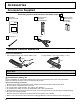
Accessories Accessories Supplied Check that you have the Accessories and items shown Operating Instruction book Remote Control Transmitter N2QAYB000323 Batteries for the Remote Control Transmitter (2 × AA Size) POS. /SIZE PICTURE DISPLAY FUNCTION PC COMPO. HDMI フ CH INPUT VIDEO MENU EXT.SCALER OFF TIMER MEM. LOAD DISPLAY Fixing band × 1 AC cord Remote Control Batteries Requires two AA batteries. 1. Pull and hold the hook, then open the battery cover. 2.
Connections When connecting the speakers, be sure to use only the optional accessory speakers. Refer to the speaker’s Installation Manual for details on speaker installation. 1 2 Speaker terminal (L) Speaker terminal (R) 2 AC cord connection (see page 13) – AC cord fixing Unplug the AC cord Close 1 Push until the hook clicks. 1 Plug the AC cord into the display unit. Plug the AC cord until it clicks. 2 Note: Make sure that the AC cord is locked on both the left and right sides.
Connections PC Input Terminals connection (Female) COMPUTER AUDIO PC IN Conversion adapter (if necessary) Mini D-sub 15p RGB PC cable Audio (Male) Stereo plug Connect a cable which matches the audio output terminal on the computer. Notes: • Due to space limitations, occasionally you may have trouble connecting Mini D-sub 15P cable with ferrite core to PC input Terminal.
Connections SERIAL Terminals connection The SERIAL terminal is used when the Plasma Display is controlled by a computer. (Male) COMPUTER 1 2 6 SERIAL RS-232C Straight cable 3 7 4 8 5 9 Pin layout for SERIAL Terminal (Female) D-sub 9p Notes: • Use the RS-232C straight cable to connect the computer to the Plasma Display. • The computer shown is for example purposes only. • Additional equipment and cables shown are not supplied with this set.
Connections HDMI connection This unit has terminal boards equivalent to Dual HDMI Terminal Board (TY-FB10HMD) and RCA Component Video Terminal Board (TY-42TM6Z) as standard equipment. [Pin assignments and signal names] Pin No. 1 2 3 4 5 6 7 8 9 10 Signal T.M.D.S Data2+ T.M.D.S Data2 Shield T.M.D.S Data2T.M.D.S Data1+ T.M.D.S Data1 Shield T.M.D.S Data1T.M.D.S Data0+ T.M.D.S Data0 Shield T.M.D.S Data0T.M.D.S Clock+ Pin No. 11 Signal T.M.D.S Clock Shield 12 T.M.D.
Power ON / OFF Connecting the AC cord plug to the Plasma Display. Fix the AC cord plug securely to the Plasma Display with the clamper. (see page 9) Connecting the plug to the Wall Outlet. Note: When disconnecting the AC cord, be absolutely sure to disconnect the AC cord plug at the socket outlet first. INPUT MENU OK Power Indicator Press the Power switch on the Plasma Display to turn the set on: Power-On.
Initial selections Selecting the input signal Select the input signals to be connected by installing the optional Terminal Boards. INPUT Press to select the input signal to be played back from the equipment which has been connected to the Plasma Display. INPUT PC HDMI1 HDMI2 HDMI3 HDMI4 COMPONENT PC COMPO.
Basic Controls Main Unit When the menu screen is displayed: “▲” : press to move the cursor up “▼” : press to move the cursor down (see page 19) INPUT button (INPUT1, INPUT2, INPUT3 and PC selection) (see page 14) Remote control sensor INPUT Main Power On / Off Switch MENU Screen ON / OFF Each time the MENU button is pressed, the menu screen will switch. (see page 19) MENU ENTER/■ Enter / Aspect button (see page 18, 19) Power Indicator The Power Indicator will light. • Power-OFF ...
Basic Controls Remote Control Transmitter POS. /SIZE button (see page 31) PICTURE button (see page 21) Standby (ON / OFF) button The Plasma Display must first be plugged into the wall outlet and turned on at the power switch (see page 13). Press this button to turn the Plasma Display On, from Standby mode. Press it again to turn the Plasma Display Off to Standby mode. LIGHT button Lights the INPUT and VIDEO MENU buttons for 5 seconds.
Basic Controls SCROLLING BAR and TEST PATTERNS functions Pressing activates one of the following two functions. The function button setting can be configured by accessing “Function button assign” in the OPTIONS menu. (see page 42) SCROLLING BAR TEST PATTERNS Press Press Press to select “YES”. SCROLLING BAR SCROLLING BAR YES NO TEST PATTERNS YES Press. Activates the SCROLLING BAR ONLY screensaver. After 15 minutes, the display enters standby mode. Press to select “YES”. TEST PATTERNS NO Press.
ASPECT Controls The Plasma Display will allow you to enjoy viewing the picture at its maximum size, including wide screen cinema format picture. Note: Be aware that if you put the display in a public place for commercial purposes or a public showing and then use the aspect mode select function to shrink or expand the picture, you may be violating the copyright under copyright law.
On-Screen Menu Displays Various menus allow you to make settings for the picture, sound, and other functions so that you can enjoy watching Display best suited for you. Remote Control POS. /SIZE PICTURE 1 Unit Display the menu screen. press PICTURE NORMAL IZE MENU SET UP PICTURE MENU POS. /SIZE PICTURE 25 SOUND BRIGHTNESS 0 SHARPNESS 5 OPTIONS COLOR TEMP STANDARD Each time the MENU button is pressed, the menu screen will switch.
On-Screen Menu Displays Overview Note: Menu that cannot be adjusted is grayout. Adjustable menu changes depending on signal, input and menu setting. PICTURE NORMAL IZE ADVANCED SETTINGS SET UP PICTURE MENU POS. /SIZE PICTURE 25 BLACK EXTENSION 0 SOUND BRIGHTNESS 0 INPUT LEVEL 0 COLOR 6 GAMMA 2.
PICTURE Adjustments 1 Display the menu screen. 2 Select “PICTURE”. During “RGB” and “PC” input signal. NORMAL IZE 2 PICTURE MENU OK STANDARD PICTURE 25 SET UP BRIGHTNESS 0 POS. /SIZE SHARPNESS 5 PICTURE 1 SOUND select COLOR TEMP NORMAL COLOR MANAGEMENT OFF ADVANCED SETTINGS 3 Select the item and set.
PICTURE Adjustments ● PICTURE Adjusts the proper picture contrast. ● BRIGHTNESS Adjusts for easier viewing of dark pictures such as night scenes and black hair. ● COLOR Adjusts color saturation. ● TINT Adjusts for natural flesh tones. ● SHARPNESS Adjusts picture sharpness. Less More Darker Brighter Less More Reddish Greenish Less More ● COLOR TEMP Switches to various screen color tones. NORMAL: Intermediate color temperature. COOL: Colors with a bluish tinge.
PICTURE Adjustments ADVANCED SETTINGS Enables fine picture adjustment at a professional level. Notes: • The adjustment values are memorized separately for each input terminal. • The adjustment range values should be used as an adjustment reference. ADVANCED SETTINGS NORMAL IZE PICTURE MENU STANDARD NORMAL IZE PICTURE 25 BLACK EXTENSION 0 BRIGHTNESS 0 INPUT LEVEL 0 5 GAMMA 2.
PICTURE Adjustments ● 3:2 PULLDOWN When “ON”, the display attempts to reproduce a more natural interpretation of sources such as movie pictures, which are recorded at 24 frames per second. If the picture is not stable, turn the setting to “OFF”. OFF ON Note: When “ON”, this setting only affects the following signal input: • 525i (480i), 625i (575i), 1125 (1080) / 60i signal input during “COMPONENT” input signal.
Picture Profiles Up to 16 combinations of picture adjustment values (in the PICTURE menu and ADVANCED SETTINGS) can be stored in the display memory as profiles and applied as needed, for a convenient way to enjoy your preferred picture settings.
Picture Profiles Saving profiles Follow these steps to save picture adjustment values as profiles. 1 Specify the picture quality in the PICTURE menu and ADVANCED SETTINGS. (see page 21-24) 2 In the PICTURE menu, select “MEMORY SAVE”. MEMORY SAVE MEMORY LOAD MEMORY EDIT 3 2 OK 1 select 5 Enter a name for the profile. [Entering profile names] Profile names can be up to 16 characters. To enter text, select characters in the on-screen keyboard.
Picture Profiles Loading profiles Load profiles and apply the picture adjustment values to the display as follows. Note: Loaded profiles are stored in memory according to the selected input interface (SLOT1, 2, 3 or PC IN). In the PICTURE menu, select “MEMORY LOAD”.
Picture Profiles Editing profiles Delete or rename profiles as follows. Note: Locked profiles and profiles currently in use cannot be deleted. Note: Locked profiles cannot be renamed. 1 1 In the PICTURE menu, select “MEMORY EDIT”. MEMORY SAVE 2 MEMORY LOAD MEMORY EDIT 2 1 MEMORY SAVE OK MEMORY LOAD MEMORY EDIT select 2 Select “MEMORY DELETE”. 2 MEMORY DELETE In the PICTURE menu, select “MEMORY EDIT”.
Picture Profiles Locking profiles You can lock saved profiles to restrict operations when the profiles are loaded. You can also set passwords. Display the menu screen. 1 2 Select “OPTIONS” and hold more. Enter a 4-digit password. The default password is “0123”. 5 Select “OK”. for 3 seconds or OK (3 seconds or more) 1 select 2 PICTURE SET UP POS.
Picture Profiles Switches to “PICTURE MENU” mode display. 1 2 Follow steps 1–5 in the previous procedure, . Select “isf Mode”. MEMORY1 Lock1 MEMORY2 Off MEMORY12 Off isf Mode Off 2 set 1 select Change password 3 4 Specify “On” or “Off”. Exit the menu. or Specifying “On” for isf Mode changes the “PICTURE MENU” mode display as follows.
Adjusting POS. /SIZE 1 Display the menu screen. 2 Select “POS. /SIZE”. During “Digital”, “SDI” and “HDMI” input signal. NORMAL IZE 2 H-POS 0 SET UP H-SIZE 0 POS. /SIZE V-POS 0 SOUND V-SIZE 0 PICTURE 3 OK 1 Select the item and set. select NORMAL IZE AUTO SETUP 4 AUTO SETUP H-POS 0 H-SIZE 0 V-POS 0 V-SIZE 0 1:1 PIXEL MODE OFF DISPLAY SIZE OFF 2 adjust or select 1 select 1:1 PIXEL MODE OFF DISPLAY SIZE OFF During “COMPONENT”, “RGB” and “PC” input signal.
Adjusting POS. /SIZE ● DOT CLOCK (During “COMPONENT”, “RGB” and “PC” input signal) Periodic striped pattern interference (noise) may occur when a striped pattern is displayed. If this happens, adjust so that any such noise is minimized. ● CLOCK PHASE (During “COMPONENT”, “RGB” and “PC” input signal) Eliminate the flickering and distortion. ● 1:1 PIXEL MODE Adjusts the display size when 1125i, 1125p or 1250i signal is input. Notes: • Select ON when you would like to replay 1920 × 1080 input signal.
SOUND Adjustment 1 Display the menu screen. 2 Select “SOUND” NORMAL IZE AUDIO MENU 2 PICTURE OK SET UP POS. /SIZE SOUND 3 Select the item and set. STANDARD BASS 0 MID 0 TREBLE 0 BALANCE 0 SURROUND 1 select 2 adjust or select 1 select VOLUME OFF 1 NORMAL IZE AUDIO MENU STANDARD BASS 0 MID 0 TREBLE 0 BALANCE 0 SURROUND VOLUME 4 OFF 1 Exit the menu. or Item AUDIO MENU BASS MID TREBLE BALANCE SURROUND VOLUME Details STANDARD: Emits the original sound.
SCREENSAVER (For preventing image retention) Do not display a still picture, especially in 4:3 mode, for any length of time. If the display must remain on, a SCREENSAVER should be used. 1 Display the menu screen. 2 Select “SET UP”. SCREENSAVER START FUNCTION 2 PICTURE OK SET UP POS. /SIZE SOUND 3 1 select 2 OK 1 select 2 change 1 select SIDE BAR ADJUST NEGATIVE IMAGE BRIGHT WOBBLING OFF PEAK LIMIT OFF Select “SCREENSAVER”.
SCREENSAVER (For preventing image retention) Reduces screen image retention These functions prevent the occurrence of an “image retention” on the display when turned ON. WOBBLING: Automatically shifts the display image (therefore unnoticeable to the eye) to prevent image retention of sharper contour of image. ON1: Shifts the image every 30 seconds. ON2: Shifts the image at a dot level pitch depending on screen-detection. PEAK LIMIT: Suppresses image contrast (peak brightness).
Specifying the scaler This menu can be used to specify whether the built-in scaler or an external scaler is used for scaler functions such as resizing and picture quality adjustment. The setting is valid with the following input signals. 1125 (1080) / 24p·25p·30p·50p·60p 1 Display the menu screen. 2 Select “SET UP”. SIGNAL SCREENSAVER COMPONENT/RGB-IN SELECT 2 PICTURE RGB OK SET UP POS.
Reduces power consumption 1 Display the menu screen. 2 Select “SET UP”. SIGNAL SCREENSAVER COMPONENT/RGB-IN SELECT 2 PICTURE SET UP POS. /SIZE 1 SOUND RGB OK select EXTERNAL SCALER MODE OFF POWER SAVE OFF STANDBY SAVE ON POWER MANAGEMENT OFF AUTO POWER OFF 3 Select the item and set.
Customizing the On-Screen Menu Display Specify the background color and display position of on-screen menus as follows. 1 Display the menu screen. 2 Select “SET UP”. SIGNAL SCREENSAVER COMPONENT/RGB-IN SELECT 2 PICTURE RGB OK SET UP POS. /SIZE 1 SOUND select EXTERNAL SCALER MODE OFF POWER SAVE OFF STANDBY SAVE ON POWER MANAGEMENT OFF AUTO POWER OFF 3 Specify the background color. Select “OSD DESIGN” and choose the background color (transparency).
SET UP for Input Signals COMPONENT / RGB IN SELECT Select to match the signals from the source connected to the COMPONENT / RGB input terminals. Y, PB, PR signals “COMPONENT” RGB signals “RGB” 1 Display the menu screen. 2 Select “SET UP”. PICTURE 2 OK 1 select SET UP POS. /SIZE SOUND 3 Select “COMPONENT / RGB-IN SELECT” and set. SIGNAL 2 SCREENSAVER change COMPONENT/RGB-IN SELECT RGB 4 EXTERNAL SCALER MODE OFF POWER SAVE OFF select RGB COMPONENT 1 Exit the menu.
SET UP for Input Signals SIGNAL menu Note: “SIGNAL” setup menu displays a different setting condition for each input signal. For RGB SIGNAL [ RGB ] SIGNAL SYNC SCREENSAVER COMPONENT/RGB-IN SELECT AUTO RGB XGA MODE EXTERNAL SCALER MODE OFF REFRESH RATE POWER SAVE OFF 33.7 kHz 60.0 Hz ON V-FREQ. POWER MANAGEMENT OFF SIGNAL FORMAT AUTO POWER OFF OFF OSD POSITION OSD LANGUAGE 100 Hz H-FREQ.
SET UP for Input Signals SYNC Select SIGNAL from the “SET UP” menu during RGB input signal. [ RGB ] SIGNAL SYNC AUTO XGA MODE 1024 ×768 REFRESH RATE 100 Hz 2 change 1 select AUTO ON G VBS Setting RGB sync signal Confirm that the input is set to RGB INPUT (this setting is valid only for RGB INPUT signal) AUTO: The H and V sync or synchronized signal are automatically selected. If both input, it is selected the H and V sync.
OPTIONS Adjustments 1 Display the menu screen. 2 3 Select “OPTIONS”. Press Onscreen display On All Aspect Off Studio mode Function button assign for more than 3 seconds. PICTURE Memory lock 2 OK (more than 3 seconds) 1 select 2 set 1 select SET UP POS. /SIZE SOUND Off Scrolling bar OPTIONS 4 Select the item and set. Onscreen display On All Aspect Off Studio mode Off Function button assign Scrolling bar Memory lock 5 Exit the menu.
Watching Videos and DVDs If you have applicable equipment connected to the Display, you can easily watch videos and DVDs using the Display’s remote control. You can select the external equipment to access. To operate other manufacturers’ equipment, you need to register the code for the equipment. (see page 44) 1 Select the input mode. (see page 14) INPUT HDMI1 DISPLAY HDMI2 INPUT HDMI3 HDMI4 COMPONENT PC PC COMPO. HDMI フ CH INPUT 2 Select the remote control mode.
Watching Videos and DVDs Programming the Remote to Operate Peripheral Equipment You can operate other manufacturers’ equipment using this Display’s remote control. 1 Connect the external equipment to the Display and Power Off the external equipment. 2 Press both buttons simultaneously for more than 3 seconds. DISPLAY + Release the buttons when the equipment selection buttons start flashing. 3 4 PC Select the equipment. COMPO.
Troubleshooting Before you call for service, determine the symptoms and make a few simple checks as shown below. Symptoms Picture Checks Sound Interference Noisy Sound Electrical Appliances Cars / Motorcycles Fluorescent light Normal Picture No Sound Volume (Check whether the mute function has been activated on the remote control.
List of Aspect Modes Aspect mode All Aspect: Factory setting On All Aspect: Off 16:9 14:9 FULL JUST JUST Pictures with a 4:3 aspect ratio are enlarged horizontally so that the picture distortion is minimized. The left and right edges of the pictures are cut off. The display of the areas around the left and right edges of the screen is slightly elongated. 4:3 4:3 (1) 4:3 H-FILL 46 Pictures with a 4:3 aspect ratio are displayed with their original aspect ratio.
Remote Control Operation / Code List The following explains how to operate external devices with the Display’s remote control. Register the remote control codes (page 44) if you want to operate an external device from another manufacturer. (see page 48, 49) Note: Operation may not be possible depending on the available memory size of the remote control. This remote control is not designed to cover operation of all functions of all models.
Remote Control Operation / Code List Remote Control Code List DBS / CABLE (Cable Set Top Box) Brand Code Brand Code Brand Code Brand Code ABC 0003, 0008, 0014, 0017 GoldStar 0144 Paragon 0000 Starcom 0003 Americast 0899 Hamlin 0009, 0273 Philips 0317, 1305 Supercable 0276 Amino 1602, 1822 i3 Micro 1602 Pioneer 0144, 0533, 0877, 1877 Supermax 0883 Bell & Howell 0014 Jerrold Pulsar 0000 Thomson 1256 Bell South 0899 0003, 0012, 0014, 0276, 0476, 0810 Quasar 0000 Toco
Remote Control Operation / Code List Remote Control Code List (Continued) DVD Recorder / Player Brand Code Brand Code Brand Accurian 1072, 1416 Fisher 0670 Marantz 0539 Sanyo 0670, 0695, 0873 Advent 1016 Funai 0675, 1268, 1334 Memorex 0695, 0831, 1270 Sensory Science 1158 Aiwa 0641 Gateway 1073, 1077, 1158, 1194 Microsoft 0522, 1708 Sharp 0630, 0675, 0752, 1256 Akai 0695, 0770, 0899, 1089 GE 0522, 0815, 0717 Mintek 0717, 0839 Sharper Image 1117 Alco 0790 Go Video 0521
Applicable Input Signals 1 2 3 4 5 6 7 8 9 10 11 12 13 14 15 16 17 18 19 20 21 22 23 24 25 26 27 28 29 30 31 32 33 34 35 36 37 38 39 40 41 42 43 44 45 46 47 48 49 50 51 52 53 Signal name Horizontal frequency (kHz) Vertical frequency (Hz) 525 (480) / 60i 525 (480) / 60p 625 (575) / 50i 625 (575) / 50p 625 (576) / 50p 750 (720) / 60p 750 (720) / 50p 1,125 (1,080) / 60p 1,125 (1,080) / 60i 1,125 (1,080) / 50p 1,125 (1,080) / 50i 1,125 (1,080) / 24sF 1,125 (1,080) / 30p 1,125 (1,080) / 25p 1,125 (1,080) / 2
Applicable Input Signals VIDEO input (HDMI) Signal format 1 2 3 4 5 6 7 8 9 10 VGA60 525/60p 625/50p 750/60p 750/50p 1125/60i 1125/50i 1125/60p 1125/50p 1125/24p Vertical Horizontal frequency (Hz) frequency (kHz) 59.94 31.47 59.94 31.47 50.00 31.25 60.00 45.00 50.00 37.50 60.00 33.75 50.00 28.13 60.00 67.50 50.00 56.26 24.00 27.00 Dot clock (MHz) 25.18 27.00 27.00 74.25 74.25 74.25 74.25 148.50 148.50 74.
Specifications TH-50VX100U Power Source Power Consumption Power on Stand-by condition Power off condition Plasma Display panel Screen size (No.of pixels) Operating condition Temperature Humidity Applicable signals Scanning format PC signals Connection terminals HDMI A-B COMPONENT/RGB IN PC IN SERIAL Speaker terminal Accessories Supplied Remote Control Transmitter Batteries Fixing band Dimensions (W × H × D) Mass (weight) TH-65VX100U 110 - 127 V AC, 50/60 Hz 605 W 755 W Save OFF 0.9 W, Save ON 0.
(for the U.S.A and Puerto Rico) Panasonic Professional Display Company Unit of Panasonic Corporation of North America One Panasonic Way 1F-10 Secaucus, NJ 07094 Panasonic Professional Flat Panel Display Limited Warranty Panasonic Professional Display Company.
(for Canada) Panasonic Canada Inc. 5770 Ambler Drive, Mississauga, Ontario L4W 2T3 LIMITED WARRANTY STATEMENT Panasonic Canada Inc. (also known as PCI) warrants this product to be free of defects in material and workmanship under normal use during the applicable warranty coverage period described below. PCI agrees to repair, or at its option, exchange, any part that becomes defective. However, the product must be purchased and serviced in Canada.
Customer’s Record The model number and serial number of this product can be found on its back cover. You should note this serial number in the space provided below and retain this book, plus your purchase receipt, as a permanent record of your purchase to aid in identification in the event of theft or loss, and for Warranty Service purposes.