。 PELONIS� en USER MANUAL Package Terminal Air Conditioner (PTAC/ PTHP) Rated voltage: 208/230V, 265V Frequency: 60Hz Warning notices: Before using this product, please read this manual carefully and keep it for future reference. The design and specifications are subject to change without prior notice for product improvement. Consult with your dealer or the manufacturer for details. PP09HMB82 PP12HMB82 PP15HMB82 Customer service: 1(866)-646-4332 www.pelonis.
Owner’s Manual 0 Safety Precautions ............................................................................ 4 1 Air Conditioner Features ................................................................. 8 2 Control Panel Operation .................................................................. 9 3 Dip Switches Configuration ........................................................... 11 4 Dip Switches Configuration By Panel Control ........................... 13 5 Wall Thermostat Terminal .........
Safety Precautions CAUTION • This appliance is not intended for use by persons (including children) with reduced physical, sensory, or mental capabilities, or lack of experience ad knowledge, unless they have been given supervision or instructions concerning the use of the appliance by a person responsible for their safety. • Children should be supervised to ensure that they do not play with the appliance.
Safety Precautions SAFETY PRECAUTIONS To prevent injury to the user or other people and property damage, the instructions shown here must be followed. Incorrect operation due to ignoring of instructions may cause harm or damage. The level of risk is shown by the following indications. This symbol indicates the possibility of death or serious injury. WARNING This symbol indicates the possibility of injury or damage to property. CAUTION WARNING • Plug in power plug properly.
Safety Precautions WARNING • Do not use the power cord near flammable gas or combustibles, such as gasoline, benzene, paint thinner, etc. It may cause an explosion or fire. • Always install a circuit breaker and a dedicated power circuit. Incorrect installation may cause fire and electric shock. CAUTION • When the air filter is to be removed, do not touch the metal parts of the unit. It may cause injury. • When the unit needs cleaning, switch off, and turn off the circuit breaker.
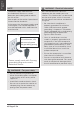
Safety Precautions NOTE WARNING - Electrical Information The power supply cord with this air conditioner contains a current detection device designed to reduce the risk of fire. Please refer to the section Operation of Current Device for details. In the event that the power supply cord is damaged, it can not be repaired. It must be replaced with a cord from the manufacturer. Grounding type wall receptacle Do not, under any circumstances, cut, remove or bypass the grounding prong.
Safety Precautions NOTE The shape may be different according to its model: Power Cord Power Supply 230V, 15A 230V, 20A 230V, 30A 265V, 15A 265V, 20A Operation of Current Device (208/230V models only) The power supply cord contains a current device that senses damage to the power cord. To test your power supply cord do the following: 1. Plug in the Air Conditioner. 2. The power supply cord will have TWO buttons on the plug head.
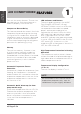
Air Conditioner Features AIR CONDITIONER FEATURES This unit has many features. The servicer must be familiar with these features in order to properly service the unit. Compressor Restart Delay This feature extends the overall life of the compressor by preventing the shorting cycling of the air conditioner. When the compressor restarts, the unit is designed to give a minimum of three minutes to have a time of equalizing the refrigerant pressures for optimizing cycling.
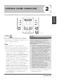
2 CONTROL PANEL OPERATION The control panel keypad will look like the following Fig. 1. For some models with REMOTE SIGNAL RECEPTOR, the unit can be controlled by the control panel alone or by the remote. Control Panel Operation cool high med °C heat low °F fan SPEED MODE temperature ON OFF POWER Press the POWER button to turn the unit on or off. When the unit is on, the power indicator light will be green. When the unit is off, the light will go out. Fig.
UP/DOWN BUTTONS ( +/-) Push the UP (or DOWN) button to increase (or decrease) the set temperature of the unit in cooling or heating mode. The temperature can be set by increments of 1° F (1°C). The setting temperature appears in the display. Control Panel Operation NOTE Press and hold “+ ” and “- ” buttons together for 3 seconds will alternate the temperature display between “°C” & “°F” scale.
DIP SWITCHES CONFIGURATIONS 3 REMOVING THE FRONT PANEL • Dip switches controls are located behind front panel, through an opening below the control panel. To access, remove front panel. See Fig. 2. Fig. 2 - Then lift up 2. • Dip switches are accessible without opening the control box. See Fig. 3. • Unit must be powered OFF to effectively change their status. Fig. 3 Dip switches DIP SWITCHES CONFIGURATIONS See Table 1 and Fig.
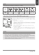
No . S1 UP (ON) Electric Heat Only S2 S3 DOWN (OFF) Electric Heat and Pump Heat Temperature Display in °C Control Panel Enable Temperature Display in °F Wall Thermostat Enable UP*UP: 61°F~86°F (16°C~30°C) UP*DOWN: 65°F~78°F (18°C~26°C) S4*S5 DOWN*UP: 63°F~80°F (17°C~27°C) DOWN*DOWN: 68°F~75°F (20°C~24°C) S6 Fan Continuous Run for Heating Fan Cycle for Heating S7 Fan Continuous Run for Cooling Fan Cycle for Cooling Low temp. protection S9 Low temp.
4 DIP SWITCHES CONFIGURATIONS by PANEL CONTROL • Turn off the unit. • Press the up (+) and down (-) buttons together for 3 seconds to activate the dip switches configurations by panel control (see Fig. 5). High (left) LED display window Low (right) 01 °C °F • See Table 2 for Dip Switches configurations and functions by panel control.
5 WALL THERMOSTAT TERMINAL (Optional) IMPORTANT Only trained, qualified personnel should access electrical panel on unit and install electrical accessories. Please contact your local electrical contractor, dealer, or distributor for assistance. • Wired Wall Thermostat Connection Instructions - Remove the two screws as shown below and take the cover panel down to enable wall thermostat Thermostat Wire Routing Thermostat wire is field supplied.
CAUTION UNIT DAMAGE HAZARD • Failure to follow these instructions may result in equipment damage or improper operation. • Improper wiring may damage unit’s electronics. Shared branch circuit is not permitted. Damage or erratic operation may result if not followed. FRONT DESK CONTROL The controller can handle a switch signal from FC (L) and FC (N) input, called front desk control. Input must be 24VAC.
6 INSTALLATION INSTRUCTIONS HOW TO INSTALL THE UNIT PREPARATION OF SLEEVE ASSEMBLY (optional) CAUTION • There are sharp edges that can cause serious cuts. • When lifting the air conditioner, it is HEAVY. Use 2 people to lift. • • Refer to the installation instruction of sleeve assembly for details. PREPARATION OF REAR GRILLE ASSEMBLY (optional) Refer to the installation instruction of rear grille assembly for details. For existing sleeve, you should measure the wall sleeve dimensions.
• Remove the front panel. (see Fig. 8) • 2 Lift unit level and slide unit into wall sleeve until firmly against front of wall sleeve and secure with 4 screws and washers (supplied in the SLEEVE ASSEMBLY) through the unit flange holes. (see Fig. 11 and Fig. 12). 1 Fig. 8 • Remove the shipping screw from the vent door - only if ventilation is desired.(see Fig. 9) Fig. 11 Shipping screw Fig. 12 • Reinstall front panel. (see Fig. 13) 1 Fig.
7 CARE AND CLEANING FRONT PANEL AND CASE Turn unit off and disconnect power supply. To clean, use water and a mild detergent. DO NOT use bleach or abrasives. Some commercial cleaners may damage the plastic parts. OUTDOOR COIL Coil on outdoor side of unit should be checked regularly. Unit will need to be removed to inspect dirt build-up that will occur on the inside of the coil. If clogged with dirt and soot, coil should be professionally cleaned of debris.
- Removing Air Filter - 2 Air Filters Reinsert the vent door steel wire into the hole of the vent door. Vent door control lever Pull up Screws Vent door steel wire Fig. 14 - Replacing Air Filter Vent door filter Vent door Fig. 16 Push down Fig. 15 VENT DOOR FILTER IMPORTANT Turn unit off before cleaning. If the vent door is open, access requires the removal of the unit from the wall sleeve. Clean the vent filter twice a year or as required.
TROUBLESHOOTING TIPS 8 POSSIBLE CAUSES SOLUTIONS UNIT DOES NOT START • Check that the plug is plugged securely in wall receptacle. If not, plug in securely. Note: Plug has a test/reset button on it. Make sure that the plug has not tripped. • Unit may have become unplugged. • Fuse may have blown. • Replace the fuse. See Note 1. • Circuit breaker may have been • Reset circuit breaker. See Note 1. tripped. • Turn unit on (bottom right button on keypad). • Unit may be off.
POSSIBLE CAUSES SOLUTONS WATER DRIPPING INSIDE • Wall sleeve is not installed level. • Wall sleeve must be installed level for proper drainage of condensation. Check that installation is level and make any necessary adjustments. • Low outdoor temperature. • When outdoor temperature is approximately 55°F or below, frost may form on the indoor coil when unit is in Cooling mode. Switch unit to FAN operation until ice or frost melts. • Dirty filters. • Remove and clean filters.
Warranty 9 PACKAGE TERMINAL AIR CONDITIONER (PTAC/PTHP) LIMITED WARRANTY Your product is protected by this Limited Warranty: Warranty service must be obtained from Midea Consumer Services or an authorized Midea servicer. Warranty • Two Year Limited Warranty from original purchase date. Five Year Limited Sealed System (Sealed system includes components containing refrigerant) Warranty from original purchase date.
This warranty does not cover the following (cont.): 4) Interior or exterior rust on the unit. 5) Failures to start due to interruption and/or inadequate electrical service, blown fuses, or open circuit breakers. 6) Service calls to instruct you on the use of your product. 7) Surcharges including, but not limited to, any after hour, weekend, or holiday service calls, tolls, ferry trip charges, or mileage expense for service calls to remote areas, including the state of Alaska.