
Use and Care Manual


10
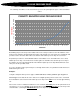
The following chart will be used to determine the pressure drop through both styles of Pensotti radiator
valves.
Determining the pressure drop for the radiator valve is the same procedure used for the radiators on the
previous page. Find the calculated flow rate in gpm on the bottom axis of the chart, move straight up until
you intersect the curve then draw a line to the left axis and read the pressure drop in feet of head.
Repeat this procedure for each individual radiator. If the radiators are to be installed in a series circuit,
add the pressure drop of each valve in the circuit together to determine the total valve pressure drop. If
the radiators are to be piped in parallel the valve with the highest pressure drop will determine the total
valve pressure drop for that circuit.
In a series circuit the total loop flow rate passes through all the valves, in a parallel circuit the flow rate is
divided among the valves.
Example:
Using the example from the previous page; a HD24-48D radiator emitting 9,926 Btu @ 0.99 gpm flow
Find 0.99 gpm on the bottom axis of the chart, move straight up until you intersect the curve, now follow
the horizontal line to the left axis and read the pressure drop for this valve in feet of head, approximately
1.0’.
If there were 3 of these radiators installed in a series circuit the total valve pressure drop would be 3 feet
of head (3 x 1.0’ = 3’). In a parallel circuit, with the same 3 radiators, the total valve pressure drop for the
circuit would be 1’, the largest individual valve pressure drop in the parallel circuit.
0
1
2
3
4
5
6
7
8
9
10
11
12
13
14
15
16
17
0.3
0.4
0.5
0.6
0.7
0.8
0.9
1
1.1
1.2
1.3
1.4
1.5
1.6
1.7
1.8
1.9
2
2.25
2.5
2.75
3
3.25
3.5
3.75
4
FEET OF HEAD
GPM FLOW
PENSOTTI RADIATOR VALVE PRESSURE DROP
H VALVE PRESSURE DROP