
Use and Care Manual


11
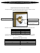
Total Piping Circuit Pressure Drop
The total circuit pressure drop is calculated by adding together the total radiator pressure drop, total H-
valve pressure drop, boiler pressure drop, and the supply and return piping pressure drop (including all
devices installed within the piping. (Flowcheck, airscoop, valves etc.).
Circulator Sizing
Circulator size is determined by two criteria; flow rate in gpm and total pressure drop in foot of head. After
these two items have been calculated for a particular piping circuit, a circulator can be chosen using the
manufacturer’s performance curve.
Example;
Three Pensotti HD12-24D panel radiators, 2,900 Btus each, installed in a series piping circuit designed
for a 20 degree temperature drop.
Flow rate = 3 x 2,900 / 10,000
Flow rate = .87 gpm
Radiator Pressure drop = 0.108 foot of head (from radiator pressure drop chart)
H-valve pressure drop = 3 foot of head (from H valve pressure drop chart)
Boiler pressure drop = 1 foot of head (from manufacturers’ information)
Supply & return pressure drop = 4.5 foot of head (calculated)
Total Piping Circuit Pressure Drop = 8.61 foot of head
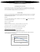
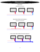
.87 gpm @ 8.61 foot of head
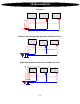
Using the manufacturer’s performance curves, choose a circulator that meets or slightly exceeds the
circuits’ requirements, see example below.
0
5
10
15
1 2 3 4 5 6 7 8 9 10 11 12 13 14 15 16 17 18
Total Head
- Feet
GPM
Circulator Curve
TOTAL PRESSURE DROP