
User's Manual


4
IntelliCenter Control System Wireless Control Panel Installation Guide
IntellliCenter Control System Wireless Control Panel Installation Guide
Wireless Control Panel Transceiver Installation
The following procedure describes how to install the IntelliCenter Control System Wireless
Controller transceiver module and connect the Transceiver cable to the COM port on the
IntelliCenter Control System main circuit board.
Note: IF YOU ARE USING MULTIPLE WIRELESS CONTROLLER: IntelliCenter Control System
Wireless Controller, be sure the Transceiver for each of these controllers are located at least 6 ft.
apart for each other. This will avoid digital interference and ensure better wireless reception.
IntelliCenter Control System Wireless Controller kit
The Wireless Control Panel kit consists of:
• Wireless Control Panel
• Wireless Transceiver
• Transceiver module Installation Instructions (P/N 522056)
• Four plastic anchors and retaining screws (to mount the transceiver module)
Mounting the Transceiver
The Transceiver is connected to the IntelliCenter Control System via the RS-485 bus. The
Transceiver is connected to the Wireless Control Panel via a 2.4GHz RF connection. Mount the
Transceiver module at a convenient location (on a flat vertical surface) near the Load Center, at
a minimum of 5 ft. above ground level to optimize the functional operating range of the wireless
control panel.
Note: To avoid signal interference, mount the Transceiver antenna a minimum of
10 ft. away from the Load Center or Power Center, any metal surface/structure, or air blower located
in the immediate area of the equipment pad.
To mount the transceiver near the IntelliCenter Control System Load Center:
1. Switch OFF the main power off to the IntelliCenter Control System Load Center.
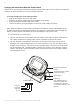
2. Remove the two retaining screws securing the transceiver case to the back plate. Carefully
slide the case off the back plate.
3.
CAUTION - Electrostatic Discharge (ESD): Hold the circuit board from the edges.
Do not touch the board components, electrostatic discharge can damage the board.
Slide the transceiver circuit board up and out of the back plate.
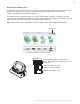
4. Position the back plate against the mounting surface so that the case is oriented in
an upright position (with the antenna pointing upwards). Use a pencil to mark the four
mounting points. Drill four 3/16 in. diameter holes into the mounting surface. If screws are
not being used, insert the four plastic wall anchors (provided in the kit).
5. Feed the provided 10 ft. of UL approved four 22 AWG conductor cable through the
knockout hole at the bottom of the enclosure. Do not run wire through the load center drain
holes. If the knockout hole is not being used to run wire through, drill a hole through the
bottom of the back plate, route the wire through the hole and seal it using a fitting with a
few feet of conduit or some other sealant between the case and the cable.