
Instruction Manual

- 4 -
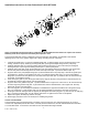
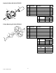
Installation Instructions for Gear Reduction Kit 9910-KIT31086
Hypro recommends a blue thread locking compound on all threaded fasteners that do not require lock washers.
Shaft key needs to be inspected occasionally and replaced if worn.
The 9910-KIT31086 gear reducer is designed for direct mounting the 9910-DP423, 9910-DP523 & 9910-DP763
diaphragm pump onto a 5 hp gasoline engine with a ange mounting and 3/4” solid shaft.
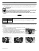
1. Lubricate the gasket (Ref. 1) in the pump adapter ange (Ref. 3). Slip the ange over the machined surface of the
casting, shaft end of pump. Install (4) mounting bolts (Ref. 4) through the adapter ange into the pump body.
2. Install the shaft hub (Ref. 6) on the pump shaft, after inserting the key (Ref. 5). Secure the hub by threading the
retaining bolt (Ref. 15) through the retaining washer (Ref. 7) into the pump shaft.
3. Install the pump gear (Ref. 8) with the pilot diameter of the gear inserted into the inner diameter of the pump shaft.
Secure rmly onto the shaft using M10 x 25 socket head cap screws (Ref. 10) and lock washers (Ref. 14).
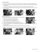
4. Align the holes in the pump adapter ange (Ref. 3) with threaded holes in the pump body. Lubricate the gasket (Ref.
9) and place it in position on the gearbox body (Ref. 13). Install the gearbox body (Ref. 13) on the pump adapter
ange (Ref. 3) and secure rmly with M10 x 75 socket head cap screws (Ref. 4). Install the M8 x 20 socket head cap
screw (Ref. 2) and tighten securely.
5. Insert the long key (Ref. 21) into the engine shaft keyway. Align the keyway in the gear reducer input shaft (Ref. 20)
and slide the pump and gear reducer onto the engine shaft.
6. Align the holes in the gearbox body (Ref. 13) with threaded holes in engine boss. Insert 5/16”x1”-24 socket head cap
screws through the gearbox body (Ref. 13) and thread them into the threaded holes in the engine boss. Securely
tighten with the hex wrench provided.
7. The vent plug (Ref. 18) must always be installed or reinstalled in the uppermost threaded hole of the gearbox body
(Ref. 13). Plugs (Ref. 11) and vent plug (Ref. 18) are interchangeable for gear reducer mounting convenience.
8. Fill the gear case with 90W gear lube. To properly ll, rst tighten the bottom plug (Ref. 11); then remove one side plug
(Ref. 11) and the vent plug (Ref. 18). Fill until the gear lube is no higher than the mark on the dipstick.
9. Replace and tighten the side plug and the vent plug.
10. Please apply anti-seize to the motor shaft prior to installing the gearbox.
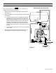
Control Unit 9910-GS25
The 9910-GS25 control unit is designed for convenient control of pressures up to 290 psi and ows up to 12 gpm. It
consists of an adjustable pressure relief valve, a manual pressure release lever, and two individual ball valve-controlled
1/2” hose barb outlets. It can be direct mounted onto the 9910-DP423 discharge manifold.
Form L-1385 (05/14)