
Instruction Manual

- 6 -
Maintenance Instructions
1. After usage, ush the pump with clean water.
2. Hypro diaphragm pumps come with oil in the crankcase. Hypro recommends changing oil after 40 hours of break-in
operation and every three months or 500 hours, whichever comes rst. Use Hypro oil (part number 2160-
0038). Hypro oil is a specially formulated, high-grade, non-detergent, SAE 30 weight oil formulated to
prolong pump life.
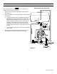
To drain the oil:
Remove the drain plug (2406-0023) and the oil sight glass covers, and rotate shaft until the oil stops owing
out. Re-install the drain plug.
To ll the pump with oil, slowly pour oil into sight tube while turning the pump shaft. Turning the pump shaft
purges all the air out of the crankcase. Always change oil when replacing diaphragms.
3. For winter storage or if a freezing condition will be encountered, ush the pump with a 50/50 mixture of water and
antifreeze.
The bypass return outlet on all control units must be connected directly to the tank without restrictions or ball
valves.
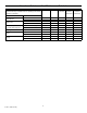
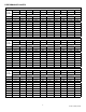
CRANKCASE OIL CAPACITIES
Oil crankcase capacities are approximate. Fill oil to proper level in sight glass. Al-
ways make sure all the air is purged out of crankcase prior to operation.
Model Capacity
9910-DP423
9910-DP573
9910-DP763
13 oz.
Valve Replacement
Occasionally debris may cause improper seating of the valves or damage to the o-rings. To check for this problem, follow
these steps.
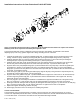
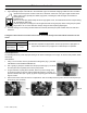
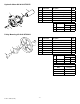
Inlet Manifold:
1. Using a 13 mm socket, remove (9) manifold mounting bolts (Fig. 1). DO NOT
USE IMPACT GUN ON MOUNTING BOLTS.
2. Pull or gently pry away the manifold from the pump heads (Fig. 2). Do this so
the valve pilots are completely free from the pump heads.
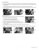
3. On gear reduction or pulley-driven models, there may not be enough room
to access the valves for service while the manifold remains in one piece. To
split the manifold, either pull or gently pry apart at opposing joints as shown in
Figures 3 and 4.
4. Remove the suction valves for service or replacement. This can usually be done by hand, but use external pliers (as
shown in Fig. 5) if necessary.
Fig. 1
Fig. 2 Fig. 3 Fig. 4
Form L-1385 (05/14)