
Installation Guide


6
W/D/V-A1
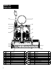
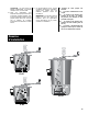
Parts List
1
2
3
4
14
6
8
7
9
10
11
12
13
15
16
5
*Replace pump
Ref
No. Part No. Description Qty.
1 26230A000 Ring Handle 1
2 14077-000-1 Pipe Plug 1
3 * Motor Housing 1
4 *
Stator/Seal Plate/Rotor and Shaft Assembly
1
5 139-014-1 Seal Ring 1
6 14770-005-1 Pan Screw 5 6
7 8521-101-1 Bottom Plate 1
8 14770-002-1 Pan Screw 6 5
9 8520-002-1 Base 1
10 8498-003-1 Impeller 1
11 21607A001 Shaft Seal 1
12 14770-001-1 Screw 1
Ref
No. Part No. Description Qty.
13 6000-053-1 Wire with Terminal 1
14 834-030-1 O-Ring 1
15 75-005-1 Cord Nut 1
16 14623-010-1 Power Cord 10’ 1
16 14623-020-1 Power Cord 20’ 1
FOR AUTOMATIC OPERATION
NOT
SHOWN
12150-110-5 Wide Angle Switch 10’ 1
12150-120-5 Wide Angle Switch 20’ 1
NOT
SHOWN
14974-000-5 Diaphragm Switch 10’ 1
14974-001-5 Diaphragm Switch 20’ 1
NOT
SHOWN
13869-510-5 Vertical Switch 10’ 1
13869-520-5 Vertical Switch 20’ 1