MasterTemp TM POOL AND SPA HEATER 120/240 VAC NATURAL GAS/LP GAS CERTIFIED ® INSTALLATION and USER’S GUIDE MODELS 200K BTU/HR 250K BTU/HR 300K BTU/HR 400K BTU/HR Natural 460730 460732 460734 460736 Propane 460731 460733 460735 460737 SPECIAL INSTRUCTIONS TO OWNER Retain this manual for future reference. This manual supplies information for the installation, operation, and servicing of the appliance. READ AND REVIEW THIS MANUAL COMPLETELY before proceeding with an installation.
Table of Contents INSTALLATION, OPERATION AND SERVICE MANUAL Safety . . . . . . . . . . . . . . . . . . . . . . . . . . . . . . . . . . . 2 General Specifications, Requirements . . . . . . . . . 3 Description of the Heater . . . . . . . . . . . . . . . . . . . 4 Sequence of Operation . . . . . . . . . . . . . . . . . . . . . 4 Owner’s Operating Instructions . . . . . . . . . . . . . . 4 Before Startup. . . . . . . . . . . . . . . . . . . . . . . . . . 4 What To Do If You Smell Gas . . . . . . . . . . . .
exhaust fumes to blow into the room housing the heater. The heater is supplied with an integral venting system for outdoor installation. A vent conversion kit (See Page 14 for Part Numbers for Conversion Kits) is available for installations in enclosures (Canada) or indoors (U.S.). Use the specified venting, and only the specified venting, when heater is installed in an enclosure or indoors.
• the high limit switch (HLS), which opens if the heat exchanger outlet temperature goes above 135° F (57° C), and • the automatic gas shutoff (AGS) switch, which opens if the heat exchanger outlet temperature goes above 140° F (60° C). • the stack flue sensor (SFS), which shuts down the heater if the flue gas temperature reaches 500° F (260° C). The air flow switch (AFS) senses the pressure drop across the air metering orifice.
C. Use only your hand to turn the gas control on or off. Never use tools. If you cannot change the ON/OFF setting by hand, don’t try to repair it, call a qualified service technician. Force or attempted repair may result in fire or explosion. D. Do not use this heater if any part has been under water. Immediately call a qualified service technician to inspect the heater and to replace any part of the control system and any gas control which has been under water. E.
8. Push the toggle switch away from you to switch the gas on. 9. Replace the Door Access Panels. All panels must be in place when operating the heater. 10. Set 3-way valves on inlet and outlet to pool or spa, as appropriate. 11. Turn on all electric power to the appliance. 12. Press either the POOL ON or SPA ON button switch on the operating control. 4. Toggle-Style Valve: Pull toggle toward you to turn gas off. 5. Replace the Access Door Panels.
The SERVICE SYSTEM light indicates that there is insufficient water flow to the heater. If the pump is operating, this usually indicates that the filter and/or skimmers should be cleaned (some filters may require backwashing). If the light remains on after the filter/skimmers have been serviced, the system should be checked by a qualified service technician. The SERVICE HEATER light indicates a fault in the heater or its controls.
into the manifold. 5. Drain the plastic inlet/outlet manifold through the outlet pipe. If the pipe does not drain naturally to the pool, install a drain cock in the outlet pipe to drain the manifold. 6. Cover air inlet grate with a plastic bag to prevent bugs, leaves, etc., from getting into the heater. NOTICE: Water trapped in the heater can cause freeze damage. Allowing the heater to freeze voids the warranty. To return the heater to service after winterizing: 1. Close drain cock and fittings. 2.
TOP ...................................3 ft. (1 m) EXHAUST SIDE................6 in. (15 cm) HEADER SIDE..................18 in. (.5 m) DOOR PANELS* ............12 in. (30 cm) Note (*) For service access it is recommended to leave at least 24 in. clearance for one of the door panels. Orient the heater for convenient access to the water connections and the gas and electrical connections. Install the heater at least 18 in. (45 cm) from any property line.
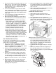
CONTROL PANEL INDEXING protection authorities about specific installation restrictions. The exhaust discharges vertically from outside the vent cover. The heater control panel assembly located on the top panel can be rotated to any of three positions for convenient access to the panel as follows: 1. Remove the bolts from the door panels. Remove both door panels. 2. Remove the four corner screws that secure the top panel. 3. Lift the top panel upward to remove the top panel. 4.
from the ceiling for ventilation air and one 12 inches (30cm) from the floor for combustion air, in accordance with the latest edition of ANSI Z223.1, or the National Fuel Gas code, the CSA B149.1, Natural Gas and Propane Installation Codes, as applicable, and any local codes that may apply. The minimum net free area in square inches are as follows: NOTICE: Combustion air contaminated by corrosive chemical fumes can damage the heater and will void the warranty (See Table 1 below).
cloth or paper towel with isopropyl alcohol (rubbing alcohol) and vigorously wipe the socket of the Vent Body. Immediately wipe the cleaned surfaces dry with a clean cloth or paper towel. Repeat for the exterior of the 4" end of the metal Flue Collar. Attach the metal Flue Collar to the Vent Body using the RTV supplied with the kit, following the vent manufacturer’s instructions (included with kit). Do not use a draft hood with this heater. 3.
5. Use Listed firestop for floor and ceiling penetrations. Use Listed thimble for wall penetrations. Use a Listed roof flashing, roof jack, or roof thimble for all roof penetrations. Do not fill the space around the vent (that is, the clear air space in the thimble or firestop) with insulation. The roof opening must be located so that the vent is vertical. 6. Do not run the heater vent into a common vent with any other appliance. 7.
pipe runs up from the heater at least 1/4" per foot (2cm/M). Install Listed condensate drains at low points where condensate might collect. Plumb condensate drains to a drain through hard piping or high-temperature tubing such as silicone rubber or EPDM rubber – do not use vinyl or other low temperature tubing. Follow drain manufacturer’s installation instructions. 5. Use Listed firestop for floor and ceiling penetrations. Use Listed thimble for wall penetrations.
4' Min. WARNING Fire Hazard. Do not run the heater vent 8. into a common vent with any other appliance. Do not run the Special Gas Vent into, through, or within any active vent such as a factory built or masonry chimney. 4' Min. 4' Min. 4' Min. Forced Air Inlet 1' Min. 4" Special Gas Vent (Vertical or Horizontal)* No. of 90° Elbows Maximum Length in Feet (M) 3' Minimum clearance if horizontal distance to exhaust opening is less than 10 feet.
Install a check valve to prevent back-siphoning through the heater when the pump is off. NOTICE: Improper operation of chemical feeders can cause severe damage to the heater which is not covered by the warranty. Install the chemical feeder downstream of the heater (see “Water Chemistry,” below). Install a chemical resistant one-way check valve between the heater and the chemical feeder. NOTICE: If you install a chemical feeder and check valve, you must install a relief valve on the heater.
on but the burner should not fire and the blower should not start. If the blower or burner do start, or if the “Service System” light does not go on, there is a pressure switch malfunction. Immediately press the OFF button on the operating control to turn the burner off and call a qualified service technician to check the system. CAUTION Live steam hazard. If the Burner and the Pump stop at the same time, wait at least 15 minutes before starting the filter pump to avoid severe damage to the heater.
PRESSURE RELIEF VALVE WARNING Explosion hazard. Any heater installed with restrictive devices in the piping system downstream from the heater (including check valves, isolation valves, flow nozzles, or therapeutic pool valving) must have a relief valve installed as described above. Canadian code requires and some U.S. local codes may require installation of a pressure relief valve.
Instructions For Checking the Gas Pressure Through the Combination Gas Control Valve WARNING Risk of fire and explosion. Improper installation, adjustment, alteration, service, or maintenance of the Combination Gas Control Valve can lead to fire or explosion, causing loss of life, personal injury, or property damage. 3.
ing system during any pressure testing of that system at test pressures in excess of 1/2 psig (3.5 kPa). The heater must be isolated from the gas supply system by closing its individual manual shutoff valve during any pressure testing of the gas supply at test pressures equal to or less than 1/2 psig (3.5 kPa). GAS CONNECTIONS The heater requires a gas supply of not less than 4" (10.2cm) wc and not more than 14" (35.6cm) wc.
Connect the L1 of the power supply to the black wire, the L2 or neutral lead to the red wire, and the ground wire to the green wire. A time clock controlling the filter pump should have a low-voltage Fireman’s Switch that switches off the heater at least 15 minutes before shutting off the pump. NOTICE: When using a timer and Fireman’s Switch, the heater’s power supply should come from the load side of the timer. The Fireman’s Switch completes the circuit for the low voltage safety switches.
6. Reinstall the access door panels. The fuse for the Fireman’s Switch is a 1.25 amp 1-1/4x1/4" fast blow fuse, available locally. MAXIMUM TEMPERATURE SET POINT 1. Unbolt and remove the Door Panels (see Figure 3, Page 5). 2. Access the control panel board on the underside of the top cover. Locate the red button on the corner of the control board (see Figure 24). 3. Push the Max. Temp. Set Point button on the back of the control board (see Figure 24). The following sequence should happen: A.
Initial Troubleshooting Only qualified, trained service technicians with appropriate test equipment should service the heater. Remember that all parts of the system affect heater operation. Before starting this troubleshooting procedure, make sure that the pump is running correctly, that there are no blockages in the system, that the valves are correctly set and that the time clock is correctly set and is running. IMPORTANT! READ ME FIRST!! on either 120 Volts AC or 240 Volts AC. 2.
Heater Will Not Fire - A Start NO Is green “SPA” or “POOL” LED “on” YES Check that correct 12-pin plug is installed (red is 240V, black is 120V) YES Depress “POOL” or “SPA” ON button on Membrane Pad. Does “POOL” or “SPA” LED come on? NO YES Check for line voltage to heater. NO Heater should fire on demand for heat. Restore power to heater. YES NO If plug is not installed: Install correct plug. 240V plug in 120V circuit: Replace with correct plug.
Heater Will Not Fire - B Start Is red “SERVICE HEATER” LED “on” NO Is red “SERVICE SYSTEM” LED on? NO YES YES Verify that pump is on, filter is not blocked, and the water flow is above the minimum requirement. NO YES With pump running, adjust Water Pressure Switch to lower pressure until ‘SERVICE SYSTEM” LED goes out. Then verify that “SERVICE SYSTEM” LED goes on with pump off. Increase POOL/SPA temperature setting on Membrane Pad above actual water temperature.
Heater Will Not Fire - C Start NO Is “SERVICE HEATER” LED “on”? YES If any red diagnostic LED’s (AGS, AFS, SFS, HLS, PS, or THERMISTOR) come “on”, go to to Pages 28 and 29. NO Go to “INITIAL TROUBLESHOOTING” Turn off power to heater for 5 seconds, and turn back on. Make sure temperature setting is above water temperature. Wait one minute. YES Does heater fire and stay on? CONTINUE NO NO Did burner fire at all? Did Blower come on? YES YES Verify that gas is flowing to burner during ignition try.
Heater Will Not Fire - D IMPORTANT! READ ME FIRST!! IMPORTANT! READ ME FIRST!! If your heater is correctly connected to 240 Volts AC, The Ignition Control Module (ICM) will convert the 240VAC to an intermittent pulse to the ignitor. Digital meters don’t read this type of signal well. (An analog meter will give a better reading than a digital meter). If the ICM is bad, your volt- meter will read either 0 VAC or 240 VAC. If your ICM is good, your meter will read some voltage between 0 and 240 VAC.
Diagnostic LED’s: AGS, AFS, HLS, PS, THERMISTOR Verify that water flow rate is above minimum required for heater. AGS or HLS “on” Replace High Limit Switch (HLS) or Automatic Gas Shutoff (AGS) NO YES YES Verify that inlet water temperature is below 104° F. Service pump and filter to restore proper flow. After servicing, verify proper operation of Pressure Switch (PS). NO Replace thermistor or Control Board to correct overheating.
Diagnostic LED’s: SFS SFS “on” Check Heat Exchanger Coil for leaks, liming, soot, or low flow. Heater starts and runs OK, but temperature of exhaust climbs to 450º–500º in 3–5 minutes. YES YES Check Thermal Regulator: Open at 120º? NO Heater starts after several tries, exhaust temperature stays below 250º. OR Heater doesn’t start at all (exhaust stays cold). Check pressure and volume of fuel supply NO YES Replace Heater Membrane Pad.
Burner Troubleshooting SYMPTOM CAUSE REMEDY Loud, high-pitched whine Flame is too rich. Verify pressure tap between gas valve and blower inlet. Turn to Page 19 and verify that the gas regulator setting is 0.2" (0.5cm) wc below the blower inlet pressure. Replace gas orifice with smaller size. Flame is “fluttery.” gas Exhaust may have acrid smell or burner may fail to stay lit. Flame is too lean. Turn to Page 19 and verify that the Burner pulsates or surges, especially on ignition.
REPAIR PARTS – BURNER SYSTEM Model Key Part No. Description 1 Combination Gas Control Valve Kit 2 3 • Gas Orifice Kit – NG (Incl. Key Nos. 3 and 4)† • Gas Orifice Kit – Propane (Incl. Key Nos. 3 and 4)† • NG to Propane Conversion Kit Qty.
1 3 4 5 2 6 7 8 9 10 11 12 13 14 15 16 17 18 19 22 21 20 REPAIR PARTS – WATER SYSTEM Model Key Part No. 1 2 3 4 5 • 6 7 8 9 10 11 12 13 14 15 16 17 18 • 19 20 21 22 * • Description Tube Sheet Coil Assembly Kit (NA, LP Series) (Includes Key No.3) Manifold Kit (Includes Key Nos. 3-14, 21, and Key Nos. 7-9 in “Electrical System”, Page 35 Coil/Tubesheet Sealing O-Ring Kit Manifold Bottom Plate Manifold O-Ring O-Ring Kit (Incl. Key Nos.
2 18 3 4 19 15 5 12 13 4 10 11 9 8 REPAIR PARTS – ELECTRICAL SYSTEM 35
Pool Heater Wiring Connection Diagram CONNECTION DIAGRAM AGS Switch Air Flow Switch Stack Flue Sensor Extra Switch 1 Gas Valve Hi-Limit Switch Y/R Y/BL Y/O Pressure Switch Y/W Y Y Y Y Y O O O O BR BR THERMISTOR HLS FS PS 24VAC R VAL TH IND GND 24VAC PR PR R Y ES1 OPERATING CONTROL AFS NA/LP Models Only J6 Y/W J6 Y 1 W Y/O Y/BL Y/R Y Y Y Y MEMB RANE PAD CONNECTIO N AGS SFS 9 JMP GAS 6 BL W Y/W 1 BL NA/LP Models: J6 incl.
Pool Heater Electrical Schematic Ladder Diagram LADDER DIAGRAM 120/240 VAC L1 L2 IGNITER L1 S1 F1 F2 S2 L2 BLOWER GND 120/240 VAC CLASS II TRANSFORMER 24 VAC OPERATING CONTROL 24 VAC 24 VAC GND AIR FLOW SWITCH LOGIC 24V TH WATER PRESSURE SWITCH HI LIMIT SWITCH IND COM NO AGS SWITCH VAL GAS VALVE STACK FLUE SENSOR THERMISTOR SENSOR NOTES: 1.) L1 S2 L2 F1 GND F2 IND S1 24 VAC VAL AND TH ARE CONNECTED ON THE IGNITION MODULE. 2. ) PIN AND SOCKET CONNECTOR. 3.
Customer Support Sanford, North Carolina (8 A.M. to 5 P.M. Eastern Standard Time) Phone: (800) 831-7133 Fax: (919) 566-8920 Moorpark, California (8 A.M. to 5 P.M. Pacific Standard Time) Phone: (800) 831-7133 SAVE THESE INSTRUCTIONS © 2006 Pentair Water Pool and Spa, Inc. All rights reserved This document is subject to change without notice 1620 Hawkins Ave., Sanford, NC 27330 • (919) 566-8000 10951 West Los Angeles Ave.