1 MiniMax CH ® POOL & SPA HEATERS OPERATION & INSTALLATION MANUAL WARNING FOR YOUR SAFETY - READ BEFORE OPERATING Warning: If you do not follow these instructions exactly, a fire or explosion may result, causing property damage, personal injury or loss of life. For additional free copies of this manual; call (800) 831-7133. To Consumer Retain For Future Reference U.S.
Table of Contents Introduction ............................................................................................................... 3 Important Notices ...................................................................................................................................................................... 3 Warranty Information ........................................................................................................................................................
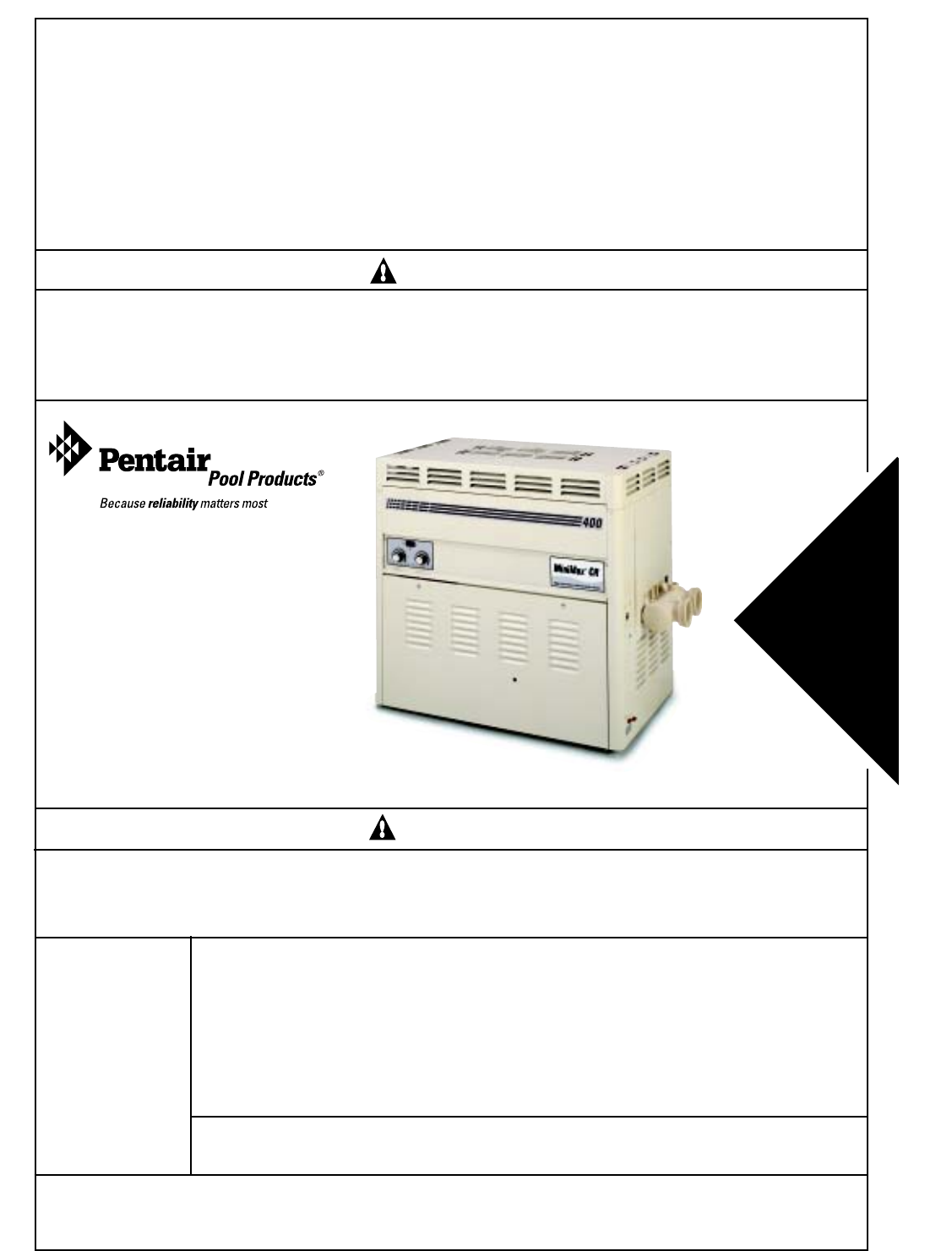
Introduction MiniMax CH Pool and Spa Heaters Congratulations on your purchase of a MiniMax CH high performance heating system. Proper installation and service of your new heating system and correct chemical maintenance of the water will ensure years of enjoyment. The MiniMax CH is a compact, lightweight and efficient gas fired high performance pool and spa heater that can be directly connected to schedule 40 PVC pipe and has a built-in top.
Operation (contd.) 4 This instruction manual provides operating instructions, installation and service information for the MiniMax CH high performance heater. The information in this manual applies to the MiniMax CH 150, 200, 250, 300, 350, and 400 natural gas and propane (LP) models. PRODUCT IDENTIFICATION It is very important that the owner/installer read and understand the section covering installation instructions, and recognize the local and state codes before installing the MiniMax CH.
Operation (contd.) 5 MINIMAX CH MILLIVOLT LIGHTING/OPERATION-NATURAL GAS & PROPANE FOR YOUR SAFETY: READ BEFORE LIGHTING WARNING If you do not follow these instructions exactly, a fire or explosion may result causing personal injury, loss of life and property damage. Since propane gas is heavier than air, escaping propane will accumulate and remain at ground level. Do not attempt to light the heater.
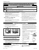
Operation (contd.) 6 OPERATING (CONTROLS) Dual Temperature Control System For convenience and economy all MiniMax CH heaters are equipped with two thermostats on the front of the heater control panel; see Figure 5. POOL THERMOSTAT KNOB STOPPER SPA OFF Each thermostat is equipped with a mechanical stop that can be locked or unlocked with use of a screwdriver to prevent temperatures in excess of that desired by the user; see Figure 6.
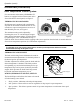
Maintenance MAINTENANCE INSTRUCTIONS It is recommended that you check the following items at least every six months and at the beginning of every swimming season. 1. Examine the venting system. Make sure there are no obstructions in the flow of combustion and ventilation air. 2. Visually inspect the main burner and the pilot burner flame. The normal color of the flame is blue. When flame appears yellow, burners should be inspected and cleaned; see Figure 8. 3.
Maintenance (contd.) 8 CHEMICAL BALANCE RULE: 7.4 to 7.6 is a desirable pH range. It is essential to maintain correct pH, see Table 2. POOL AND SPA WATER If pH becomes too high (over alkaline), it has these effects: Your Pentair Pool Products pool heater was designed specifically for your spa or pool and will give you many years of trouble free service provided you keep your water chemistry in proper condition.
Installation Instructions SPECIFICATIONS IMPORTANT NOTICE: These installation instructions are designed for use by qualified personnel only, trained especially for installation of this type of heating equipment and related components. Some states require installation and repair by licensed personnel. If this applies in your state, be sure your contractor bears the appropriate license.
Installation (contd.) POOL 10 THERMOSTAT SELECT OFF SPA COLD POOL TEMP HOT COLD SPA MANUAL BY-PASS TEMP HOT PUMP TO POOL POOL HEATER FILTER 3 MANUAL BY-PASS 1 ISOLATION VALVE CHECK VALVE Where the flow rate exceeds the maximum 120 GPM, a manual bypass should be installed and adjusted. After adjustments are made, the valve handle should be removed to avoid tampering. ISOLATION VALVE 1 2 3 Optional. Required when installation is below water level.
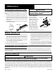
Installation (contd.) 11 WATER CONNECTIONS INSULATING THE HIGH LIMITS Reversible Inlet/Outlet Connection When Reversing Heads on the MiniMax CH Heater The MiniMax CH heater is factory assembled with right side inlet/outlet water connections. The inlet/ outlet header can be reversed for left side water connections without removing the heat exchanger. Reversing Water Connections Disassembly Tools needed: 1/4 in Nut Driver 9/16 in. Socket and Wrench 1/2 in. & 9/16 in.
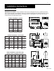
Installation (contd.) 12 GAS CONNECTIONS GAS LINE INSTALLATIONS Before installing the gas line, be sure to check which gas the heater has been designed to burn. This is important because different types of gas require different gas pipe sizes. The rating plate on the heater will indicate which gas the heater is designed to burn. Tables 7-9, on pages 12 and 13, shows which size pipe is required for the distance from the gas meter to the heater. The table is for natural gas at a specific gravity of .
Installation (contd.) 13 Pipe Sized For Length Of Run In Equivalent Feet, (cont’d.) PROPANE 2 STAGE REGULATION In many “RESIDENTIAL” Propane gas line installations, the gas supplier and or installer will utilize a two stage regulation process where by at the supply tank they will install the first stage gas regulator, which would be at a higher pressure, usually 10 psi and can be for longer distance and in a smaller pipe size.
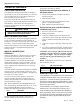
Installation (contd.) 14 VENTILATION STACK TYPE OUTDOOR VENT KIT OUTDOOR INSTALLATION ONLY For outdoor installation with built in vent top, the heater must be placed in a suitable area on a level, noncombustible surface. Do not install the heater under an overhang with clearances less than 3 feet from the top of the heater. The area under an overhang must be open on three sides. IMPORTANT! Model Vent Cap Product No. Vent Dia. 150 OV15 460237 6 in. 200 OV20 460222 7 in.
Installation (contd.) 15 INDOOR INSTALLATION (USA ONLY) OUTDOOR SHELTER INSTALLATION (CANADA) All products of combustion and vent gases must be completely removed to the outside atmosphere through a vent pipe which is connected to the draft hood. A vent pipe extension of the same size must be connected to the draft hood and extended at least 2 feet higher than highest point of the roof within a 10 foot horizontal radius, and at least 3 ft.
Installation (contd.) 16 NOTE The heater requires two uninterrupted air supply openings; one for ventilation and one to supply oxygen for proper gas combustion. The air supply openings should be sized according to Tables 12. and 13. BASE FOR USE ON COMBUSTIBLE FLOORS T O H TM CE RMAN PERFO R HEATE HIGH . in ES EL TC Air supply requirements below apply to all MiniMax heaters All opening sizes are minimum and unobstructed. POOL HT RE OM TS TA SPA M 6 HOT TEMP SPA COLD COLD 6 " M in .
Installation (contd.) 17 ELECTRICAL MiniMax CH Millivolt Wiring Diagram MINIMAX WIRING DIAGRAM (MILLIVOLT) DUAL THERM (HONEYWELL ELECTRONIC) IF ORIGINAL FACTORY WIRING MUST BE REPLACED, INSTALLER MUST SUPPLY UL OR CSA (IF CANADA) APPROVED WIRE, 18 GAUGE, 600V, 105 C˚ TEMPERATURE RATING. THERMAL FUSE WIRING MUST BE REPLACED WITH UL OR CSA (IF CANADA) APPROVED WIRE, 18 GAUGE, 600V, 125 C˚ TEMPERATURE RATING.
Troubleshooting - General Possible Cause Remedy Heater will not come on Pump not running Place pump in operation Pump air locked Check for leaks Filter dirty Clean filter Pump strainer clogged Clean strainer Defective wiring or connection Repair or replace wires Defective pressure switch Replace switch Defective gas controls Call serviceperson On-Off switch in "OFF" position Turn switch to "ON" Heater Short Cycling (Rapid On and Off Operation) Insufficient water flow Clean filter and pump strainer Def
MINIMAX CH HEATER - ALL MODELS 32 H O T INNER TOPS M ode l No. Part No. 150 470024 200 470025 250 470026 300 470027 350 470028 400 470029 31 30 28 2 1a 29 3 37 4 20 1 15 27 23 24 16 22 18 25 26 21 5 34 7 19 6 35 9 8 36 17 33 14 10 11 12 Rev.
MiniMax CH Parts List ITEM DESCRIPTION QTY 150 200 250 300 350 400 1 Vent kit assy. (indoor) 1 460227 460228 460230 460231 460233 460234 1a Vent kit assy.
MiniMax CH Parts List, contd. ITEM DESCRIPTION QTY 150 200 250 300 350 400 31 Flue collector 1 073864 075622 073863 075623 075624 073862 32 Outdoor top assy.
NOTES P/N 472128 Rev.
1 1 23 MiniMax CH (150 IID Model) ® POOL & SPA HEATERS OPERATION & INSTALLATION MANUAL (APPENDIX) WARNING FOR YOUR SAFETY - READ BEFORE OPERATING Warning: If you do not follow these instructions exactly, a fire or explosion may result, causing property damage, personal injury or loss of life. For additional free copies of this manual; call (800) 831-7133. U.S.
Operation 24 MINIMAX CH (150 IID) ELECTRONIC IGNITION LIGHTING/OPERATION - NATURAL GAS FOR YOUR SAFETY: READ BEFORE LIGHTING WARNING If you do not follow these instructions exactly, a fire or explosion may result causing personal injury, loss of life and property damage. Do not attempt to light the heater if you suspect a natural gas leak. Lighting the heater can result in a fire or explosion which can cause personal injury, death, and property damage. C.
Operation (contd.) 25 MINIMAX CH (150 IID) ELECTRONIC IGNITION LIGHTING/OPERATION - PROPANE FOR YOUR SAFETY: READ BEFORE LIGHTING NOTE The MiniMax CH propane models have special features for additional safety and protection. Read the safety instructions for natural gas (page A-2) before proceeding. WARNING If you do not follow these instructions exactly, a fire or explosion may result causing personal injury, loss of life and property damage.
Operation (contd.) 26 OPERATING (CONTROLS) Dual Temperature Control System - (Electronic and Millivolt Models) For convenience and economy all MiniMax CH heaters are equipped with two thermostats on the front of the heater control panel; see Figure 3. THERMOSTAT ADJUSTMENT The knob with locking feature eliminates the need for constant thermostat adjustments. Set the knob pointer to the desired pool or spa temperature.
Operation (contd.) 27 SERVICE (SERVICE) The service light is off during normal operation of heater. The light only comes on if a problem with a control has occurred or when the heater is first firing. The problem must be investigated by the serviceman prior to attempts to fire the heater again. HEAT (HEAT) The heat light is on any time the thermostat has signaled a call for heat which initializes the ignition safety firing circuit -- the light comes on to indicate successful firing of the main burners.
Operation (contd.
Installation 29 REGULATED MANIFOLD PRESSURE TEST Regulator Adjustment Cap 1/8" NPT Plug (Inlet Press) 1. Attach the manometer to the heater jacket. 2. Shut off the main gas valve. ON 3. Remove 1/8 in. NPT plug on the outlet side of the valve and screw in the fitting from the manometer kit. OFF 1/8" NPT Plug (Manifold Press) 4. Connect the manometer hose to the fitting. 5. Fire the heater. REGULATOR ADJUSTMENT CAP 6. The manometer must read 4 in. WC for natural gas, 11 in.
BLK WHT/BLK WHT/RED RED GRN L2-1 L1-1 W1 A-8 POOL P5 COM P8 SPA P6 POOL OFF SPA J5 J8 J6 AUX. CONTACTS 1 P9 J9 TPROBE 1 THERMOSTAT SELECT SWITCH CLOSE ON CALL FOR HEAT CONTROL RELAY J3 J7 1 JI0 VLV PI0 BLK BLK P11 THERMOSTAT J11 CIRCUIT BOARD 1 IGN MODULE 1 J2 P7 TEMPERATURE PROBE GRN MV PV/MV PV IGNITION WIRE PV BLU 3 J4 24V P4 MV/PV ORG MV RED GRN IGNITION RETURN RED WHT BLU F2 THERMAL FUSE F1 WHT 4 25D K .032 D.
Installation (contd.) 31 REMOTE SWITCH DUAL THERM IID ONLY JUMPER REQUIRED IF NO 2 WIRE REMOTE SWITCH 3 Wire Remote EXT SWITCH 24 VAC OUT PRESS HILMT TFUSE VALVE IGNITION MOD RETURN THERMOSTAT CIRCUIT BOARD SPA COM POOL TPROBE REMOTE POOL/OFF/SPA THERMOSTAT SELECT SWITCH FRONT PANEL POOL/ OFF/SPA THERMOSTAT SELECT SWITCH Figure 7.
MINIMAX CH HEATER - 150 IID MODEL 32 H O T INNER TOP M ode l No. Part No. 150 470024 31 30 28 2 1a 29 3 37 4 20 1 15 27 23 24 16 22 25 26 6 21 5 7 19 18 34 9 35 8 36 37 33 14 10 11 12 P/N 472128 13 A-10 17 38 Rev.
MiniMax CH Parts List - 150 IID Model ITEM DESCRIPTION QTY 150 1 Vent kit assy. (indoor) 1 460227 1a Vent kit assy. (outdoor) 1 460237 2 Return header 1 070994 3 Bolt, heat exchanger 16 471991 4 Washer 3/8" ID 1" OD 16 072184 5 Tube seal gasket 18 070951 6 Electronic Thermostat circuit board - IID Model 1 470179 7 Switch rocker (single pole & double throw) 1 470186 Control panel assy. (complete) - IID Natural 1 472151 Control panel assy.
MiniMax CH Parts List - 150 IID Model, contd. ITEM DESCRIPTION QTY 150 31 Flue collector 1 073864 32 Outdoor top assy.
NOTES Rev.
40 36 SAVE THESE INSTRUCTIONS. Pentair Pool Products, Inc. 1620 Hawkins Ave., Sanford, NC 27330 • (919) 774-4151 10951 W. Los Angeles Ave., Moorpark, CA 93021 • (805) 523-2400 P/N 472128 Rev.