OWNERS OPERATION MANUAL WARNING FOR YOUR SAFETY - READ BEFORE OPERATING Warning: If you do not follow these instructions exactly, a fire or explosion may result, causing property damage, personal injury or loss of life. WARNING Improper installation, adjustment, alteration, service or maintenance may cause property damage, personal injury or death. Installation and service must be performed by a qualified technician or service agency.
OWNERS SECTION - TABLE OF CONTENTS 1. OPERATIONAL INSTRUCTIONS .............................................................................................. 3 - 7 a. Introduction & Design Features b. Heater Control Panels & L.E.D. Status Lights 2. START UP PROCEDURES ........................................................................................................... 8 - 13 a. Compressor Warm Up Time b. Filter System Cleaning c. Operational Description c. Circulation Pump Timer d.
WARNING THE MISUSE OF THIS PRODUCT CAN RESULT IN SEVERE INJURY, DEATH, OR PROPERTY DAMAGE. BE ADVISED OF THE FOLLOWING CONDITIONS THAT MAY EXIST: 1. ELECTROCUTION AND/OR FIRE DUE TO IMPROPER WIRING. 2. HAND AND HAIR ENTRAPMENT MAY OCCUR NEAR THE FAN LOCATED ON THE TOP OF THIS UNIT. 3. LOSS OF POOL WATER AND/OR FLOODING AND/OR PROPERTY DAMAGE. 4. DAMAGE AND/OR MISUSE TO THE PRODUCT RESULTING IN FAILURE OR EXCESSIVE WEAR. 5. ALL ELECTRICAL WORK BY LICENSED PROFESSIONAL ONLY.
SPECIAL FEATURES Separate Air Handling / Electric Compartment An internal electrical compartment substantially reduces future service from moisture and salt laden air flow. Quiet High Volume Fan With Vinyl Coated Guard Sturdy Rust Proof Fiberglass Top Non Fading Large Aluminum & Copper Lanced Fin Evaporator Air Coil and Coil Guard Product Name Plate Chemical Warning Label Automatic Diagnostics With L.E.D.
DESIGN ADVANTAGES The electrical panel has an isolated compartment, located within the mechanical compartment to prevent corrosion there. The heat from the compressor located just below the electrical compartment helps eliminate moisture as well. This exclusive design will substantially extend the life cycle of the heater. The fiberglass cabinet is corrosion proof and is much stronger than plastic cabinets.
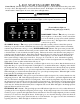
DUAL THERMOSTAT CONTROL PANEL L.E.D. Status Lights THERMOSTAT ( See page 7 for details.) The thermostat dial is just like any other, when you set it at a certain setting the heater will heat up to that temperature and then shut off. When the pool/spa water temperature drops below this setting the heater will come on and start heating the water back up to the setting on the thermostat. You will notice there are no number settings printed on the dial face.
L.E.D. STATUS LIGHT PANEL Control Ready "Green": The green control ready indicator light lets you know that the heater has power and it is ready to heat. This light must be on before the heater can run. If this light is off, check you power supply and circuit breakers. If this light is off, none of the others will light either. CAUTION The unit may still have "live voltage" when the control light is off. NOTE: The bottom four indicator lights work in sequence from left to right.
START UP PROCEDURES TURN T-STAT ALL THE WAY DOWN Make sure the thermostat dial is turned all the way to the “LEFT” so the unit will not start until you are ready. Then turn the circuit breaker on. WATER FLOW & EXISTING WATER PUMP To filter the pool water each day, the water pump will come on & off according to the existing timer device. The heater will only heat if there is water running through it.
OPERATIONAL SEQUENCE THERMOSTAT CONTROL & SETTINGS Turning up the thermostat will start the unit running. When the pool water has been heated to the thermostat setting, the unit will shut off. When the pool water temperature loses one to two degrees, the thermostat will activate the unit. There are no temperature graduate numbers printed on the thermostat face. To obtain an exact temperature, turn the t-stat all the way up and then place a pool type thermometer in the pool water itself.
TIME CLOCK SETTING Now that all the filters are clean and the pump is running with a full prime, you will need to set the pool circulation pump timer. Set the filter pump time clock for a long enough period of time to heat the pool or spa. The heater will not operate unless there is water running through the heat exchanger supplied by the circulation pump. Therefore, your pool will only heat during the period set on the timer.
THERMOSTAT SETTING There are no temperature reading numbers printed on the thermostat dial due to calibration changes from unit to unit. The demand for exact temperatures should be regulated by using a high quality thermometer right in the pool water. Normal temperatures for pools are 78 to 82 degrees F. Spa temperatures are 98 to a maximum of 104 degrees F.
UNDERSTANDING HEAT LOSS It is important to understand how your pool loses heat. The greatest heat loss occurs at the water surface. You will need to adjust the operational time to compensate for added heat loss during the colder months. See the diagram on the next page. There are four types of heat loss to be concerned with: Evaporation accounts for the greatest amount of heat loss. As the water changes from a liquid to a vapor it requires heat taken from the pool.
CONTROLLING HEAT LOSS TYPICAL POOL BLANKET & ROLLER A good way to control heat loss is to slow the wind speed through your pool area by placing plants such as shrubs or bushes around the pool's perimeter. Plants will break up the air flow and diffuse the wind speed. If the pool area is to be fenced in, choose a wood shadow box type design. Using a pool cover can be somewhat cumbersome but they are worth the trouble in regards to the great cost savings.
OWNERS MAINTENANCE & CARE There are some considerations that should be taken concerning the environment where your heater is installed. The heater is usually placed near the pool filtering system. There are certain things in this area you will need to be aware of to insure long life and prevent unnecessary damage. SPRINKLERS Make sure there are absolutely no sprinkler heads near the heater that will in any way spray on or into the heater. Sprinkler damage is not covered under the warranty agreement.
AIR FLOW Do not install the unit in an area where the cooler discharge air may accumulate and be drawn back into the unit. Provide ventilation through containment walls or fencing for the air intake if needed. Do not install this unit indoors or in filtering system equipment rooms. Do not restrict the air flow in any way. ROOF RUN OFF To prevent large amounts of rain water from running through the unit you may need to install a gutter and down spout when the roof has a sharp pitch.
FILTER SYSTEM MAINTENANCE REQUIREMENTS WATER FLOW FILTER CLEANING & CARE Proper water flow is critical to the heaters performance and longevity. The maintenance of your filtering system is directly related to the proper operation of the heat pump. See pages 8 for other information regarding filter cleaning and the start up procedures. Your filter system should be cleaned at least twice a month. See manufacturer's directions for proper filter cleaning methods.
AUTOMATIC POOL VACUUMS Automatic pool cleaners will decrease the water flow by restricting the suction of the circulation pump. Most automatic type pool cleaners operate from the suction provided by the circulation pump. Some automatic pool vacuums are plugged into the skimmer suction port. The main floor drain is then restricted some, so that the auto vac has enough vacuum to operate. It can then move freely and not become stuck to the main drain port.
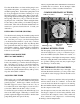
PLUMBING & WATER FLOW PLUMBING CONNECTIONS Filtered Water “IN” on the LEFT front. Heated Water "OUT" on the RIGHT front. The plumbing inlets are "slip" p.v.c. pipe that will accept a 2 inch p.v.c. glue fitting. The pipe is left plain so you can adapt to your needs. Use p.v.c. cleaner to prime the fitting and pipe. Use a quality medium body p.v.c. glue. FOR PUMPS UP TO 2 H.P. OR 90 G.P.M. MAX. SEE PAGE 19 FOR LARGER WATER PUMPS. WATER IN WATER OUT Filter Warning No Chemicals In Skimmer !! 1. PUMP 2.
HIGH RATE WATER PUMPS EXCESSIVE FLOW BYPASS MANIFOLD FOR LARGE 2 H.P. PUMPS OR OVER 90 G.P.M. If the pool circulation pump is over 2 HP OR if the total flow exceeds 90 GPM you will have to add the "excessive flow valve" as shown here. Do not install a bypass valve that will completely shut off flow to the heater, see shutdown procedures. Some larger water pumps may be restricted if the pipe size is not adequate therefore reducing its overall flow rate.
WATER BALANCE MAINTENANCE The chemical balance of your pool/spa water and the methods used in adding pool chemicals will directly effect the life of your heater. Like no other precaution you could take, it is very important that these guidelines are followed in order to prevent damage to the heat exchanger/water coil and possibly the entire system. Improperly maintained water balance and incorrect introduction of pool chemicals will cause extreme corrosion to the heat exchanger.
These chemical outlines should not be considered as a “how to” balance your pool/spa water, but just a reference on how chemical balance effects the heater and gives suggested test values. You should always consult a pool professional and follow all chemical manufacturers directions, unless they conflict with this manual. The pH level in your pool should be maintained within the range of 7.4 to 7.8. A pH test will tell you how acetic or how alkaline the pool water is.
TOTAL ALKALINITY CALCIUM HARDNESS Total Alkalinity is a test given to determine the overall mineral content of the water. Total alkalinity levels should be within the range from 90 p.p.m. to 120 p.p.m. The total alkalinity is described as a buffer against acetic conditions and acts as a stabilizer for the pH. It keeps the pH from fluctuating up and down. A low alkalinity will allow the pH to fluctuate, usually to the acetic side. A high alkalinity may cloud the water.
CHLORINATOR PLACEMENT 1. All chlorinators should have a chemical resistant check valve and a loop plumbed at least 8 inches above the chlorinator, between it and the heater, as far down line from the heater as possible. 2. Never plumb a chlorinator into the suction side of the circulation pump. All automatic chemical feeders should be as far down line of the heaters water flow as possible. 3. Off line type chlorinators should be tapped into the plumbing only as shown on the diagram.
COMMERCIAL FEEDERS We strongly suggest that all chemical feeders be placed "down line" of the heater. In a "closely monitored" commercial pool situation where a vacuum type filter system is used in conjunction with a surge tank, there are some exceptions to chemical injection. Some liquid chlorine (sodium hypochlorite) feeders and liquid muriatic acid feeders will inject their solutions into the surge tank on the suction side of the unit.
SHUT DOWN & FREEZE PROTECTION PROCEDURES When shutting the unit down for the end of the swimming season you must consider some items to protect the unit from inclement weather. It is best in most situations to shut the unit off by turning the thermostat all the way down, to the "left". Leave power ,(circuit breaker), to the unit “on” unless the pool or spa water temperature drops below 50 degrees F.
OWNER TROUBLE SHOOTING GUIDE WARNING Risk of electrical shock or electrocution. Improper installation will create an electrical hazard which could result in death or serious injury to pool users, installers, or others due to electrical shock, and may also cause damage to property. Do NOT attempt any internal adjustments inside the heater. 1. Keep your hands and hair clear of the fan blades to avoid injury. 2. If you are not familiar with your pool filtering system and heater: a.
Control Ready light ON. Water Press. OK light ON T-Stat On light ON Fan is not turning. Unit will not start. Low water flow through heater. Dirty or worn filters or clogged lint traps. Clogged filter pump impeller. Improper plumbing valve settings. Clean entire filtering system and or replace filter element. Inspect & clean pump impeller. Adjust plumbing valves. Call the factory for advice. All control lights ON Fan is turning, no cool air discharging out the top of heater. Unit is not heating.
ELECTRICAL WIRING SPECIFICATIONS WARNING The heater must be electrically grounded and bonded in accordance with local codes, or in the absence of local codes, with the latest national electrical codes ANSI/NFPA No. 70. All wiring must comply with all local codes, or in the absence of local codes, with the latest national electrical codes ANSI/NFPA No. 70. For proper wire and/or breaker size, please refer to specification sheet and your local licensed electrician.
HOW TO GET SERVICE When you experience trouble with your unit, you should follow these simple procedures before requesting service on your pool/spa heat pump. 1. You should follow all start up procedures as described in this booklet. Without exception you should clean the filtering system thoroughly, consult the manufacturers directions for proper filter cleaning methods. You must eliminate any water flow or filtering system problems. Check all electrical service, breakers and switches. 2.
GLOSSARY OF TERMS A/C Contractor: A company licensed by the state and local authorities to perform heating ventilation and air-conditioning installation or repair including pool heat pumps. Allow no others to repair this unit. Broadcast Type Sprinklers: Part of an irrigation system used to water plants or grass where the water is sprayed into the air and distributed directional. Acetic: Describing pool/spa water that is aggressive in nature with a Ph value below 7.6. Like acid, orange juice, vinegar etc.
Circuit Breaker: An automatic switch that will shut the power off to an electrical device (heater, circulation pump) when an overload or short occurs. Located in the electrical supply panel in your home or near the associated equipment. Down Line: A reference that pertains to chlorinator placement and chemical application meaning, to introduce such, into the water flow piping, after it passes through the heater, as far away from the unit as possible.
Floating Thermometer: A thermometer that floats on the water surface with the main sensing bulb in the water. Indicates the actual pool or spa temperature it’s floating in. A tie on type will work the same. Flow Control Valve: A valve or check valve that controls water flow either automatically or manually. Freon™: Trade name for a type of refrigerant. The heat transfer medium used to transfer the generated heat to the pool water, in the vapor compression cycle of the heat pump system.
Serial Number: A twelve digit number on the identification sticker on the outside of the heater cabinet. Needed for all records, warranty request etc. Shadow-Box Fence: A fence that is made to allow air to pass through it freely without restriction. Shock Treatment: Adding a larger than normal dose of chlorine to the pool water to kill contaminates, algae and to remove combined chlorine. Short Cycle: The act of the compressor going on and off without letting the refrigerant gas to settle.
This page is blank.
This page is blank.
Heat Pumps Manufactured by: © 2001 HydroTemp Manufacturing Co., Inc. 941-768-1555 www.warmpool.