
Pool Products Slide Backwash Valve Installation and Operation Manual


Page 3
Section 1. SVLV8 Installation
1. Remove the Slide Valve from the packaging. Twist
the handle on the Slide Valve several times to
verify that the piston moves freely.
FOR YOUR SAFETY: This product must be installed and serviced by authorized personnel qual i fi ed
in pool/spa installation and maintenance. Improper installation and/or operation will void the warranty.
WARNING
Ensure that all electrical power to the system is turned off before approaching, inspecting or
troubleshooting any leaking valves that may have caused other electrical devices in the surrounding
area to get wet.
This document gives instructions for installing the
Jandy Slide Valve. The instructions must be followed
exactly. Read through the instructions completely before
starting the procedure. Please save these instructions.
The Jandy Slide Valve is designed to be used on either
sand or diatomaceous earth (DE) filters with a center to
center dimension of eight (8") inches (center of the inlet
port to the center of the outlet port). Combined with the
Jandy Versa-Coupler, the Slide Valve can be used on
filters with center to center dimensions of seven (7") to
nine (9") inches.
For Jandy Filters, Slide Valve p/n SVLV8 (with unions)
is ready to mount to DEL48 or DEL60 model filters
(in which the top port is the filter outlet). If mounting a
Jandy Slide Valve on Pentair or Sta-Rite Filters, use a
combination of p/n SVLV2 (Slide Valve without unions)
and p/n 8044 (Versa-Coupler Kit).
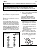
The Slide Valve is a two position valve. The valve
handle must be fully extended or fully depressed. This
valve can not be throttled. To operate the Slide Valve
on a DE filter in normal filtration mode, fully depress
the handle. To operate the Slide Valve on a sand filter
in normal filtration mode, fully extend the valve handle
(see Figure 1).
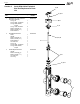
Figure 2. O-ring Placement
Coupling Nut
O-ring
Union Tail Piece
WARNING
Ensure that all electrical power to the system
is turned off before approaching, inspecting or
troubleshooting any leaking valves that may have
caused other electrical devices in the surrounding
area to get wet.
2. Turn off all power to the system. For retrofi t
installations only, follow steps "a" through "d".
For new installations skip steps "a" through "d"
and proceed to step 3.
a. Open the pressure relief valve on top of the
fi lter. Wait for all air to evacuate the system.
b. If the fi lter is below pool level, close the
suction and return line valves to isolate the
fi ltration system.
c. Remove the drain plug from the fi lter. Let the
water drain from the fi lter.
d. Remove the existing valve from the fi lter.
3. Remove the o-rings (2 total) from the packaging.
4. Place the o-rings on the face of the union tail
pieces, where the face of the Slide Valve union
will connect to the fi lter bulkheads (see Figure 2).
Make sure each O-ring is properly seated into the
groove of each union tail piece.
Figure 1. Handle Positions - Filter/Circulation
Mode(SVLV2 shown)
DE Filter
Handle fully depressed
(pushed down)
Sand Filter
Handle fully
extended
(pulled up)