ThermalFlo ™ Heat Pump Installation and User's Guide IMPORTANT SAFETY INSTRUCTIONS READ AND FOLLOW ALL INSTRUCTIONS SAVE THESE INSTRUCTIONS
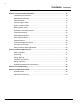
Customer Service If you have questions about ordering Pentair Water Pool and Spa replacement parts, and pool products, please use the following contact information: Customer Service (8 A.M. to 5 P.M. — Eastern and Pacific Times) Phone: (800) 831-7133 Fax: (800) 284-4151 Technical Support Sanford, North Carolina (8 A.M. to 5 P.M. — Eastern Time) Phone: (919) 566-8000 Fax: (919) 566-8920 Moorpark, California (8 A.M. to 5 P.M. — Pacific Time) Phone: (805) 553-5000 (Ext.
i Contents Important Safety Precautions .............................................................................................. iii Section 1: Introduction ..................................................................................................... 1 ThermalFlo Overview .............................................................................................. 1 General Features .....................................................................................................
ii Contents, continued Section 3: Operating the ThermalFlo ............................................................................... 15 Initial Start-up Precautions ...................................................................................... 15 Operating the Controller .......................................................................................... 16 Controller Panel .......................................................................................................
iii IMPORTANT SAFETY PRECAUTIONS Important Notice: This guide provides installation and operation instructions for the ThermalFlo HP models of Heat Pumps. Consult Pentair Water with any questions regarding this equipment. Attention Installer: This guide contains important information about the installation, operation and safe use of this product. This information should be given to the owner and/or operator of this equipment after installation or left on or near the heat pump.
iv IMPORTANT SAFETY PRECAUTIONS (continued) Consumer Information and Safety The ThermalFlo series of heat pumps are designed and manufactured to provide many years of safe and reliable service when installed, operated and maintained according to the information in this manual and the installation codes referred to in later sections. Throughout the manual, safety warnings and cautions are identified by the “ “ symbol. Be sure to read and comply with all of the warnings and cautions. WARNING — The U.S.
v IMPORTANT SAFETY PRECAUTIONS (continued) Swimming Pool Energy Saving Tips It is important to note that a heat pump will not heat a pool as fast as a large gas or electric pool heater. If the pool water is allowed to cool significantly, it may take several days to return to the desired swimming temperature. For weekend use, it is more economical to maintain the pool water temperature at or near your desired swimming temperature.
vi IMPORTANT SAFETY PRECAUTIONS (continued) General Installation Information 1. Installation and service must be performed by a qualified installer or service agency, and must conform to all national, state, and local codes. 2. The ThermalFlo heat pump gets electrical power from an external source and provides a dual electronic thermostat control system for pool/spa combinations or preheat convenience. 3. This heat pump is specifically designed for heating fresh water swimming pools and spas.
1 Section 1 Introduction ThermalFlo Overview The ThermalFlo heat pump gets electrical power from an external source and provides a dual electronic thermostat control system for pool/spa combinations or preheat convenience. ThermalFlo HP heat pumps transfer the heat from the outside air to your pool, providing the most energy efficient pool and spa heating available.
2 General Features • Dual digital thermostats offer precise temperature control to maintain the desired separate water temperatures in pool/spa combinations without overheating or wasting energy. • Long-life corrosion resistant composite cabinet stands up to severe climates and pool chemicals. • High efficiency Trane® compressor is the most energy efficient, durable, and quiet compressor available.
3 Section 2 Installation The following general information describes how to install the ThermalFlo heat pump. Note: Before installing this product, read and follow all warning notices and instructions starting on page iii. Installing the ThermalFlo Only a qualified service person should install the ThermalFlo heat pump. Materials needed for Installation The following items are needed and are to be supplied by the installer for all heat pump installations: 1. Plumbing connections (2 inch). 2.
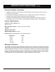
4 ThermalFlo Heat Pump Dimensions 38.7" 30.7" WATER PRESSURE REMOTE THERMOSTAT POOL SPA HEATING POWER/ MODE COOLING AUTO-HEAT/COOL TEMPERATURE SETTING POOL SPA PRESS ANY ARROW ONCE TO CHECK SET TEMPERATURE A ETL LISTED C US CONFORMS TO UL STD 1995 3044065 CERTIFIED TO CAN/CSA STD C2 2.2 NO. 236 PART NUMBER SERIAL NO. CONTAINER ID PRODUCT SPEC LABEL ThermalFlo™ HP 11.25" 9.25" 4.5" 6.5" .5" MODEL NUMBER Dimension "A" 500 700 900 1200 1200C 1200R H/C 33.5” 33.5” 41.5” 41.
5 Clearances All criteria given in the following sections reflect minimum clearances. However, each installation must also be evaluated, taking into account the prevailing local conditions such as proximity and height of walls, and proximity to public access areas. The heat pump must be placed to provide clearances on all sides for maintenance and inspection. 1. At least 24 in. [61cm] access must be available in the front and 12 in. [30 cm] on all the other sides of the heat pump for service, see Figure 2.
6 Drainage and Condensation Condensation will occur from the evaporator coil while the unit is running and drain at a steady rate, usually three to five gallons per hour, depending upon ambient air temperature and humidity. The more humid the ambient conditions, the more condensation will be produced. The bottom of the unit acts as a tray to catch rainwater and condensation. Keep the drain holes, located on the bottom pan of the base of the unit, clear of debris.
7 Anchor Clamp(s) Installation, continued 6. Drill a hole in the cement using a masonry drill bit, with a diameter as determined by the concrete anchor, at each of the marks on the equipment pad. The hole should be approximately 1½ in. deep. 7. Insert a bolt anchor into each of the holes. Be sure the anchors are set completely into the holes 8. Position the anchor clamps so that the holes in the clamps are over the bolt anchors.
8 Water Connections at the Heat Pump Two inch Quick Connect fittings have been installed on the water inlet and outlet connections, see Figure 7. Filtered cool water is plumbed to the inlet, located on the right side of the heat pump front panel. Heated water flows through the outlet, located on the left side of the heat pump front. Water Inlet Union Plastic piping (PVC Schedule 40) should be connected to the heat pump. The unions, provided with the unit, accept 2 in. PVC pipe.
9 Multiple Unit Installation Heat Pump, Heater and/or Solar Combination In certain regions of the country it may be more economical to run a heat pump during the warmer months and a gas heater during the cooler months. In some situations it may be desirable to run the heat pump in the “Chiller” mode, if so equipped, during the hottest portion of the year and a heater during the cooler months.
10 Multiple Heat Pump Connections All plumbing on multiple heat pump installations must be done in parallel see Figures 9 and 10. An equal flow of water to each heat pump is important for optimum operation. NOTE: It may be necessary to adjust water pressure switch if a unit is installed below the water level. See page 20 for details on when and how to adjust the pressure switch. Each heat pump allows a maximum flow rate of 125 gpm and requires a minimum of 30 gpm. 24 inches min. clearance around evap.
11 Electrical Connections WARNING —Risk of electrical shock or electrocution. This heat pump contains wiring that carries high voltage. Contact with these wires could result in death or serious injury to pool or spa users, installers, or others due to electrical shock, and may also cause damage to property. Always disconnect power circuit before connecting the heat pump. CAUTION — Label all wires prior to disconnection when servicing controls. Wiring errors can cause improper and dangerous operation.
12 Wiring Diagram 460812, 460813, 460814, 460815, 460822, 460804 Heat Pump Control Board PO OL SP A REMOTE CO M 10K Thermistor SO SO R LE NO ID AU 24 VAC BLUE TBL YELLOW WHITE WHITE BLACK BLACK RED Water Pres Sw Hi Ref Pres Sw Switch factory set to H for 460812, 460813, 460814, 460815, set to C for 460804, and set to AU for 460822 (on back of circuit board) PR ES C FA N CO M LO PR W ES RE S H HI P W AT E R FL OW TEMPERATURE THERMISTER RED Lo Ref Pres Sw 1 2 3 4 5 6 7 8 Optional
13 Relay Remote Controls Electrical wiring must be in accordance with the latest edition of the NEC (NFPA 70) in the United States and CEC (CSA 22.1) in Canada, unless local code requirements indicate otherwise. To connect remote control equipment to the heat pump, perform the following steps: 1. Turn off the power to both the remote pool/spa control system and the heat pump. 2. Remove the front left panel of the heat pump cabinet, (you do not need to remove the torque head screw at the top left corner).
14 Connecting the ThermalFlo to the IntelliTouch® or EasyTouch® Load Center To connect the ThermalFlo cable to the Personality Board in the IntelliTouch or EasyTouch Load Center: 1. Turn off the main system power before making any connections. 2. Unlatch the front door spring latche(s), and open the front door of the IntelliTouch or EasyTouch Load Center. 3. Loosen the two retaining screws from the top of the control panel and lower the control panel down to access the Personality Board. 4.
15 Section 3 Operating ThermalFlo This section describes how to operate the ThermalFlo heat pump. Initial Start-up Precautions CAUTION — Do not use this heat pump if any part has been under water. Immediately call a qualified service technician to inspect the heater and replace any part of the control system which has been under water. CAUTION — Keep all objects off the top of the heat pump. Blocking air flow could damage the unit and may void the warranty.
16 Operating the Controller An advanced microprocessor based controller that provides a sophisticated yet simple interface to operate your heat pump for maximum efficiency and enjoyment of your pool, controls the ThermalFlo HP heat pump. It will control incoming water temperature between a minimum of 60º and a maximum of 104º F. The controller also serves as system status indicator, using LED lights and error codes, see Figure 15.
17 Indicator Lights / LEDs Nine lights can be seen from the front of the control panel. Five are system indicators and four are mode indicators. These lights help the operator and service person understand the operation of the heat pump and aid in troubleshooting problems. System Indicator LEDs 1. WATER PRESSURE: On when in REMOTE, POOL or SPA mode and sufficient water is flowing through the heat pump. 2. THERMOSTAT: On when the controller is calling for heating or cooling. 3.
18 Operation Temperature Setting The heat pump comes factory set at 78º F. for POOL mode and 100º F. for SPA mode. Start by selecting either the POOL or SPA mode to turn the heater on, then using the “Up” and “Down” arrows, you can set the thermostat anywhere between a minimum temperature of 60º F. and a maximum of 104º F. Mode Selection Buttons 1.
19 Troubleshooting The control panel contains a three digit LED display. These LEDs display temperatures, lock out status and error codes. The error codes are listed below: CODE NAME CAUSE E01 Low Refrigerant Pressure Low refrigerant pressure switch open. E02 High Refrigerant Pressure High refrigerant pressure switch open. E03 Remote Error Pool and Spa remote inputs on simultaneously. E04 Switch Fault SW1 position indeterminate.
20 Water Pressure Switch Adjustment CAUTION — The water pressure switch should be adjusted to turn the heater off when the pump is off. Setting the switch to close at too low of a flow can damage the appliance. Adjust the switch to turn the heater off, not on. The pressure switch is preset at the factory for activation at 1.5 psi [10 kPa]. This factory setting works for all basic installations as shown previously on pages 7, 9-10 in this manual.
21 Section 4 General Maintenance Water Chemistry Proper chemical balances are necessary for sanitary bathing conditions as well as ensuring your heat pump’s long life. Be sure to keep your chemical and mineral concentration levels within the values indicated in Table 1. Failure to maintain proper water chemistry may void the warranty. Test Recommended Level Free Chlorine or 1.0 to 3.0 ppm (3.0 to 5.0 spa) Bromine 2.0 to 4.0 ppm (3.0 to 5.0 spa) pH 7.4 to 7.
22 Spring Start-Up If your heat pump has been winterized, perform the following steps when starting the system in the Spring: 1. Uncover the heat pump and inspect the top and sides for any debris or structural problems. 2. Connect the water inlet and outlet unions located on the lower front panel of the heat pump. 3. Turn on the filter pump to supply water to the heat pump. Open the filter air bleeder and circulate water through the system long enough to bleed all the air out of the pool system.
23 Professional Maintenance and Service The Pentair ThermalFlo Heat Pump is one of the most efficient ways to heat a pool or spa. The heat pump transfers heat from the outside air to the pool or spa water by means of an internal heat exchanger. When the fan is turned on, warm air is drawn through the R410A refrigerant charged air coil, turning the cold liquid refrigerant to a warm gas. The gas then flows through the reciprocating compressor, which increases the pressure and refrigerant temperature.
24 ThermalFlo Installation and User’s Guide
25 Section 5 Troubleshooting Use the following troubleshooting information to resolve possible problems with your ThermalFlo heat pump. WARNING — RISK OF ELECTRICAL SHOCK OR ELECTROCUTION. Improperly installation will create an electrical hazard which could result in death or serious injury to pool users, installers, or others due to electrical shock, and may also cause damage to property. Do NOT attempt any internal adjustments inside the heater. 1.
26 Problem Possible Cause Corrective Action Remote, Pool or Spa light ON. Water Pressure light ON. Thermostat light OFF. EO1 Error Unit will not run. Low or restricted water flow through heater. Dirty or worn filters or clogged lint traps. Clogged filter pump impeller. Improper plumbing valve settings. Suction leak allowing air into the water flow. Low water flow when switched to spa mode. Unit is plumbed backwards. Heat exchanger clogged with debris.
27 Problem Possible Cause Corrective Action Compressor will not start. Fan comes on, compressor attempts to start but unit shuts all the way off (and or circuit breaker trips). Low or restricted water flow through heater. Dirty or worn filters or clogged lint traps. Clogged filter pump impeller. Improper plumbing valve settings. Suction leak allowing air into the water flow. Low water flow when switched to spa mode. Compressor was not preheated properly. Low, weak or damaged start capacitor.
28 Section 6 Replacement Parts Illustrated Parts SEE DETAIL A DETAIL A ThermalFlo Installation and User’s Guide
29 Replacement Parts List Item No. Part No.
30 Notes ThermalFlo Installation and User’s Guide
TF
P/N 473426 Rev.