WHOLE HOUSE TANNIN SERIES SALT BASED FILTER 1.5, 2.
TABLE OF CONTENTS System Information ......................................................................................................................................3 Maintenance Requirements ..........................................................................................................................4 Pre-Installation Instructions ..........................................................................................................................4 Installation Instructions ......
SYSTEM INFORMATION POWER REQUIREMENTS The computer board receives power from an external wall-mount transformer, supplied with each system. Voltage: The voltage supplied to the computer board is 24V AC. Frequency: The line frequency is 50 Hz or 60 Hz. WATER PRESSURE A minimum of 20 pounds of water pressure is required for proper operation of the system. The stated operating pressure range is 20 psi - 120 psi (138 kPa - 828 kPa).
MAINTENANCE REQUIREMENTS SALT RECOMMENDATIONS Two kinds of salt are recommended: 1. Block Salt: Water conditioner block salt is reasonably priced, low in impurities and will not cake in the salt container. Block Salt is pressed into the shape of a cattle block. 2. Solar Salt: Solar Salt is 98% pure salt, reasonably priced and low in impurities. Solar Salt is in the shape of pellets.
INSTALLATION INSTRUCTIONS 1. SAFETY PRECAUTIONS • To prevent accident or injury, do not hoist the unit over your shoulder. Use a hand truck to transport the unit. Note: Do not lay the unit on its side during transportation and/or installation. • Wear safety glasses and work gloves during installation and service. 2. TEST THE WATER HARDNESS • The test strip provided is for testing the water hardness after the installation is complete to ensure the system is functioning properly and for periodic testing.
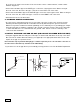
As a last resort, install a check valve. If the check valve causes “water hammer”, install a water hammer suppressor. • Connect the raw water pipe to the INLET pipe connection of the bypass valve. When looking at the front of the unit, the inlet is the pipe connection on the LEFT side of the valve. • Connect the treated water pipe to the OUTLET pipe connection of the bypass valve. When looking at the front of the unit, the outlet is the pipe connection on the RIGHT side of the valve.
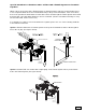
Special attention for situations where a Filter and a Tannin System are installed together: When a whole house filter and a Tannin System are installed side by side, the preferred approach is to run a separate drain line from each unit all the way to the point of termination. If this is not done, there is the potential for drain water from the filter to back feed through the Tannin System and overfill the brine tank, especially when drain lines are run overhead.
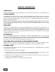
CONTROL INFORMATION POWER ON LED A green LED is ON when power is applied to the control and the microprocessor is operating properly. SERVICE REQUIRED If the message “For Service Call” or “Service Required” displays in the window of the control without showing the time of day, the control valve has encountered a problem, such as failure to reach the proper position during regeneration. The valve, the motor assembly, and board must be checked to diagnose and fix this problem.
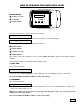
HOW TO PROGRAM THE INSTALLER’S LEVEL KEY BUTTONS: SCROLL BUTTON UP ARROW POWER DOWN ARROW To begin, verify that the control is in the Service Mode. Time of Day GL Remaining • Press the DOWN ARROW and hold it for 5 seconds; the control will display: System Check • Within 10 seconds, enter the following key sequence: DOWN ARROW DOWN ARROW SCROLL BUTTON DOWN ARROW The control is now in the Installer’s Level. Use the SCROLL BUTTON to advance through the different settings.
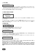
3. SALT LEVEL The control will display: Salt Level: Med • Press the UP or DOWN ARROW to select Low, Medium, or High. Medium is a good setting for most circumstances. For small families and low hardness, Low will provide greater salt efficiency. For large families and high hardness, High will provide the most capacity. Press the SCOLL BUTTON to advance to the next setting. 4.
ADVANCED MENU 1. RESET AVERAGE The control will display: Reset Average No • If you want to reset the average daily volume, press the UP or DOWN ARROW to select YES. •If YES is selected, the control will reset the average volume per day to 25 % of the capacity. Press the SCROLL BUTTON to advance to the next setting. 2. RESERVE CAPACITY The control will display: Rsrv: Variable • The reserve capacity will be calculated automatically, based on the registered daily water consumption.
Press the SCROLL BUTTON to advance to the next setting. 5. CYCLE 1 - BACKWASH The control will display: Backwash: 10 min 6. CYCLE 2 - BRINE/SLOW RINSE The control will display: BRN/RNS: 74 min Press the Up or Down ARROW to change the length of the brine/slow rinse cycle. The minimum length is preselected based on unit size and salt level, and cannot be reduced. The maximum setting is 99 minutes. Press Down Arrow to exit Installer’s Mode.
UNDERSTANDING THE DIAGNOSTIC LEVEL To begin, verify that the control is in the Service Mode. Time of Day GL Remaining • Press the UP ARROW and hold it for 5 seconds; the control will display: Regen _ Days Ago The control is now in the Diagnostic Level. Use the SCROLL BUTTON to advance to each diagnostic. If no button is pressed within 5 minutes, the display will return to the Service Mode.
SYSTEM START UP INSTRUCTIONS 1. Confirm the system is plumbed in correctly: inlet on left, outlet on right. 2. DO NOT add salt yet. If you made any mistakes, make the necessary corrections before continuing with the startup procedure. 3. When turning the water back on to the house, leave system in bypass mode. Then turn water on to house and check for leaks. Run the cold water in bathtub to flush debris and air from lines. (Bathtubs do not have aerators that may plug with debris.) 4.
VALVE EXPLODED VIEW 15
VALVE PARTS LIST 16 ITEM QUANTITY PART # DESCRIPTION 1 1 70793 3/4” NPTF TO 1/2” I.D. HOSE MALE DRAIN ELBOW 2 1 75053 72175 BACKWASH FLOW CONTROL 2.5 GPM (UNIT SIZE 1.0 & 1.5) BACKWASH FLOW CONTROL 3.5 GPM (UNIT SIZE 2.
CONTROL EXPLODED VIEW 4 6 5 10 9 7 2 3 1 8 12 20 3 14 13 11 22 17 16 18 19 21 15 17
CONTROL PARTS LIST 18 ITEM QUANTITY PART # DESCRIPTION 1 1 39497 FRONT COVER ASSY, PENTAIR ROTARY 2 1 38751 BOARD ASSY SOFTENER WITH 2 LINE DISPLAY 3 3 70618 SCREW #4-24 X 3/8 LG SELF-THREADING 4 1 72519 FLOW METER SENSOR CABLE NGC 5 1 72134 HEYCO BUSHING, SR 5P-4 6 1 70971 POWER LEAD 7 1 70312 HEYCO BUSHING, SR 2P-4 8 1 70962 ELECTRONIC CONTROL BACKPLATE 9 3 71502 SCREW #8-18 X 3/8 LG, SELF-THREADING 10 4 71497 SCREW #10-16 X 1 LG, TYPE BT SS, SELF-THREADING 11
BYPASS VALVE EXPLODED VIEW AND PARTS LIST BYPASS VALVE ASSEMBLY PART NUMBER 72668 ITEM QUANTITY PART # DESCRIPTION 1 2 72599 SCREW 6X32X1/2 TYPE 2 1 72580 BYPASS END CAP 541 3 1 13328 017 O-RING 8730 4 2 72584 RETAINING RING VS-15 5 2 71161 568-363 NUT, BYPASS VALVE 6 2 71162 568-364 RING, NUT RETAINER 7 2 71110 568-320 GASKET 8 1 72669 BYPASS BODY ROTARY 9 2 72585 O-RING 220 EPC 70 DURO 10 2 72586 O-RING 222 EPC 70 DURO 11 2 72583 SEAL BYPASS VALVE 12 2 72
SYSTEM EXPLODED VIEW AND PART LIST 6 4 4 5 2 3 1 20 ITEM QUANTITY PART # 1 1 38571 BRINE TANK BLACK 18X33 ASSY 38946 10” PENTAIR PRINTED TANK COLLAR 1.5 38947 12” PENTAIR PRINTED TANK COLLAR 2.0 38257 10 X 54 TANK BLACK W/BASE 1.5 38258 12 X 48 TANK BLACK W/BASE 2.0 83493 PENTAIR ROTARY VALVE 1.5 WITH BYPASS 83494 PENTAIR ROTARY VALVE 2.0 WITH BYPASS 18962 RISER PIPE ASSY 1.5 38013 RISER PIPE ASSY 2.
Tank Size DIM A DIM B DIM C 10x54 12x48 10-1/4 in 12 in 55-7/8 in 50 in 61-1/4 in 55-1/4 in 3 in 8 3/4 in 14 1/2 in 4 3/4 in Ø DIM A DIM B DIM C 33 1/2 in Ø 18 1/2 in 21
TROUBLESHOOTING GUIDE SYMPTOM 1. Hard (untreated) water to service 2. The unit fails to regenerate CAUSE SOLUTION 1. Open bypass valve. 1. Close the bypass valve. 2. Loss of resin. 2. Refer to SYMPTOM #9. 3. The valve is in regeneration. 3. Wait for the regeneration to complete. 4. Excessive water use. 4. Check the frequency of regenerations. 5. Change in raw water hardness. 5. Adjust settings accordingly. 6. The unit fails to regenerate. 6. Refer to SYMPTOM #2. 7.
TROUBLESHOOTING GUIDE SYMPTOM 3. The valve fails to draw brine CAUSE SOLUTION 1. Low operating pressure. 1. Verify the operating pressure (20 psi min.). 2. The injector is plugged. 2. Clean the injector. 3. The injector filter is plugged. 3. Clean the injector filter. 4. The drain line is restricted. 4. Check the drain line for kinks or restrictions. Verify that the backwash flow control is free of debris. 5. The brine line is restricted. 5. Check the brine line for kinks or restrictions. 6.
TROUBLESHOOTING GUIDE SYMPTOM 7. The unit uses too much salt 8. Salt water to service 9. Loss of resin through the drain line 10. Loss of water pressure 11. Constant water flow to the drain CAUSE SOLUTION 1. Excessive water in the brine tank. 1. Refer to SYMPTOM #5. 2. The unit regenerates too frequently. 2. Check the hardness, salt, reserve capacity and calendar override settings. 1. Excessive water in the brine tank. 1. Refer to SYMPTOM #5. 2. Low water pressure. 2.
Water Treatment Systems Limited Product Warranty STATEMENT OF LIMITED PRODUCT WARRANTY Limited Warranty Coverage For Pentair product(s) Softeners and Tank filters. The products are warranted to be free from defects in material and/or workmanship under normal use and service for the following: The Resin/Media tank and Brine tank (if applicable), will carry a ten (10) year warranty from the date of shipment. The valve body will also carry a (10) year warranty.
Notes 26
Notes 27
18345 BISHOPS DR., SUITE 200, BROOKFIELD, WI 53005 USA PENTAIR.COM | CUSTOMER SERVICE: 800.811.3489 | systems-tech-support@pentair.com All indicated Pentair trademarks and logos are property of Pentair. Third party registered and unregistered trademarks and logos are the property of their respective owners. ©2020 Pentair. All rights reserved.