Total Construction Solutions Electronic Instruction Manual Total Station R-315EX(NX) R-325EX(NX) R-335EX(NX) R-322EX(NX) R-323EX(NX) R-326EX R-300X Series BASIC 2-5-2 Higashi-Oizumi / Nerima-ku, Tokyo 178-0063, Japan Tel.: +81-3-5905-1222 / Fax: + 81-3-5905-1225 E-mail: international@piic.pentax.co.jp Website: http://www.pentax.co.jp/ppc www.pentaxR300X.
Before using this product, be sure that you have thoroughly read and understood this instruction manual to ensure proper operation. After reading this manual, be sure to keep in a convenient place for easy reference. Copyright © 2005 PENTAX Industrial Instruments Co., Ltd. All Rights Reserved PENTAX Industrial Instruments Co., Ltd. is a sole proprietor of the PTL software. The PTL software and publication or parts thereof, may not be reproduced in any form, by any method, for any purpose.
PRECAUTIONS REGARDING SAFETY Safety precautions (Must be followed) The following items are intended to prevent possible injury to the user or other people and/or damage to the instrument before it occurs. These safety precautions are important to the safe operation of this product and should be observed at all times. Distinctive displays The following displays are used to distinguish precautions by the degree of injury or damage that may result if the precaution is ignored.
PRECAUTIONS REGARDING SAFETY WARNING Do not stare into the laser beam directly as this may result in damage to your eyes. R-300X is a Class II Laser product. (The reflectorless type is a Class IIIa (3R) laser product.) Do not look into the laser radiation aperture directly as this may result in damage to your eyes. Never use the telescope to view intense light such as direct sunlight or sunlight reflected through a prism as this may result in loss of sight.
PRECAUTIONS REGARDING SAFETY CAUTION For security, please do the opening inspection and inspection every a fixed period and adjustment. When the laser beam enters eyes, an unexpected accident might be caused by the blink of eyes. Establish the laser product to avoid the height of eyes of a driving person and walker. Establish an instrument so that laser beam does not hit a reflection thing as a mirror and a glass window. The refection beam of the laser is also harmful to the human body.
PRECAUTIONS REGARDING SAFETY Usage precautions Surveying instruments are high-precision instruments. In order to assure that the Electronic Total Station R-300X series product which you have purchased will provide long-lasting maximum performance, the precautions in this manual must be followed. Be sure to follow these instructions and use this product properly at all times. [Solar observation] WARNING Never view the sun directly using the telescope as this may result in loss of sight.
PRECAUTIONS REGARDING SAFETY • • • • There is a possibility that the instrument cannot calculate correctly when receiving reflected laser beam from forth and back directions in case of measuring the target on the road. There is a possibility that synthesized values are calculated and the distance may become longer or shorter than the actual one when the operator measure the target of slope or sphere or rugged shape.
PRECAUTIONS REGARDING SAFETY [Storage and operating environment] • • • • • • • To prevent making short-circuit when removing the battery and charger from the case and storing them, apply electrically resistant tape to the poles of the battery. Storing the battery and charger as is may result in fire or burn injury due to short-circuit. Avoid storing the instrument in places subject to extreme high, low or radically fluctuating temperature.
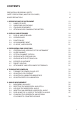
CONTENTS PRECAUTIONS REGARDING SAFETY SAFETY PRECAUTIONS (MUST BE FOLLOWED) USAGE PRECAUTIONS 3 3 6 1. BEFORE USING THE INSTRUMENT 1.1 NAMES OF PARTS 1.2 UNPACKING AND PACKING 1.3 STANDARD EQUIPMENT 1.4 ATTACHING AND CHARGING THE BATTERY 12 12 14 14 15 2. DISPLAY AND KEYBOARD 2.1 DISPLAY AND KEYBOARD 2.2 OPERATION KEY 2.3 FUNCTION KEY 2.4 ALPHANUMERIC INPUT 2.5 LD POINT, LASER POINTER 18 18 18 19 21 21 3. PREPARATION FOR SURVEYING 3.1 CENTERING AND LEVELING OF THE INSTRUMENT 3.2 LASER PLUMMET 3.
6. DISTANCE MEASUREMENT 6.1 TARGET SETTING 6.2 DISTANCE MEASUREMENT 6.3 QUICK MODE 39 39 41 42 7. CORRECTION MODE 7.1 CHANGING THE TARGET CONSTANT 7.2 CHANGING THE TEMPERATURE 7.3 CHANGING THE ATMOSPHERIC PRESSURE 7.4 CHANGING THE PPM VALUE 43 43 44 45 46 8. INITIAL SETTING 8.1 OVERVIEW 8.2 ENTERING THE MODE FOR INITIAL SETTING 1 8.3 ENTERING THE MODE FOR INITIAL SETTING 2 8.4 ENTERING THE MODE FOR INITIAL SETTING 4 8.5 ENTERING THE MODE FOR INITIAL SETTING 5 8.6 SETTING OF [DATE AND TIME] 8.
13. APPENDIX 13.1 ERROR MESSAGES 13.2 ATMOSPHERIC CORRECTION 13.3 HPA AND MMHG CONVERSION TABLE 13.4 ERROR WHEN NO ATMOSPHERIC CORRECTION IS MADE 13.5 ATMOSPHERIC REFRACTION AND EARTH CURVATURE CORRECTION 13.6 DISTANCE RANGE 70 70 71 72 72 73 74 14.
1. BEFORE USING THE INSTRUMENT 1.
Top handle Objective lens Centering knob R-335EX (NX): Shift type • Dual display panel is an optional accessory.
1.2 Unpacking and packing [Unpacking the Instrument from the case] 1 Set the case down gently with the lid facing upwards. 2 Open the latches while pressing down on the lock (safety mechanism) and open the lid of the case. 3 Remove the instrument from the case. [Packing the instrument in the case] 1 Make sure the telescope is fairly level and lightly tighten the telescope clamp screw. 2 Line up the housing marks (round yellow marks on the instrument) and tighten the upper and lower clamp screws.
1.4 Attaching and charging the battery [Removing the battery] 1 Turn the lock lever anticlockwise and remove the battery. 2 Lift up the battery pack and remove it from the instrument. • Be absolutely sure to turn the power off when removing the battery as removing the battery while the power is still on may result in damage to the instrument. 1 2 [Attaching the battery] 1 Align the guide grooves on the battery pack with the guide grooves on the instrument and push the top of the battery pack into place.
[Charging the battery] • The battery BP02 is not charged at our factory shipment so charge it. • For BP02 charge, use the special BC03 charger. Power supply cord AC adaptor Charger [Connection of code] 1 Insert the output plug of the power supply code in Jack of the AC adaptor. 2 Insert the output plug of the AC adaptor in Jack of the charger. 3 Insert the power supply plug of the power supply code in the outlet of AC power supply.
1 2 3 4 5 Power supply lamp (red) : Turns on when the power supply is turned on. Charge lamp (green): Turns on while charging and turns off when the charge is completed. Discharge lamp (yellow): Turns on when you push the discharge button. Turns off when the discharge is completed. Installation lamp (red): Blinks or turns on when the battery packing is attached normally. Blinks when charge or discharge and turns on when charge is completed.
2. DISPLAY AND KEYBOARD 2.1 Display and keyboard Alphanumeric and +/- key Enter key Power supply key Function key Illumination key ESC key Laser plummet and Electronic vial key 2.2 Operation key Key [POWER] [ESC] [ILLU] [ENT] [LASER] [Alphanumeric] [HELP] 18 Description ON/OFF of power supply Returns to previous screen or cancels an operation. Turns the illumination of the LCD display and telescope reticle on and off. Accepts the selected (highlighted) choice or the displayed screen value.
2.3 Function Key Display F. Key MODE A [MEAS] F1 [TARGET] F2 [0 SET] [DISP] F3 F4 [MODE] F5 MODE B [S.FUNC] [ANG SET] F1 F2 [HOLD] F3 [CORR] F4 [MODE] F5 Description Pressing this key one time measures the distance in normal mode another measurement type can be selected by Initial Setting 2. Pressing this key twice measures the distance in coarse mode another measurement type can be selected by Initial Setting 2. Select the target type by following order.
Other functions [ ] [ ] [ ] [ ] [RETICLE] F1 F2 F1 F2 F3 [ ] [LCD] F3 F4 [ ] [ILLU] F4 F5 [CLEAR] [SELECT] F5 F5 Moves the cursor to the left. Moves the cursor to the right. Goes back five items on the screen. Goes forward five items on the screen. Changing the reticle illumination when pressing illumination key. Moves the cursor up. Changing the LCD contrast when pressing illumination key. Moves the cursor down. Changing the LCD illumination when pressing illumination key. Clear the figure.
2.4 Alphanumeric input The point name is inputted by the alphanumeric keys as following. Key [0] [1] [2] [3] [4] [5] [6] [7] [8] [9] [.] [+/-] Letter under key PQRS TUV WXYZ GHI JKL MNO ABC DEF Letter & figure order to input [@][.][_][-][:][/][0] [P][Q][R][S][p][q][r][s][1] [T][U][V][t][u][v][2] [W][X][Y][Z][w][x][y][z][3] [G][H][I][g][h][i][4] [J][K][L][j][k][l][5] [M][N][O][m][n][o][6] [??][?][!][_][ ][^][|][&][7] [A][B][C][a][b][c][8] [D][E][F][d][e][f ][9] [.
3. PREPARATION FOR SURVEYING 3.1 Centering and leveling of the instrument [Setting up the instrument and the tripod] 1 Adjust the tripod legs so that a height suitable for observation is obtained when the instrument is set on the tripod. 2 Hang the plumb bob on the hook of the tripod, and coarse center over the station on the ground.
3.2 Laser plummet [Laser plummet model] The laser plummet is not set to be ON at factory shipping. The laser plummet operation of power supply ON can be set by command No 520, LD PLUM & E VIAL. For using Command number, refer to 9-2. Accessing by 007. [For the Detaching type laser plummet equipment model] Turn on the laser plummet function by pushing the Laser key. Match the position with the leveling screw so that the laser mark coincides with the ground mark.
• • • • • The brightness adjustment step of the laser is 10 steps. The laser plummet spot can become difficult to see in bright sunlight which makes it difficult to perform the occasional check. In this case, use your foot or the carrying case to make a shadow over the laser position. The laser plummet is adjusted to be within ±0.8mm at the instrument height of 1.5m at factory shipping.
3.4 Leveling with circular vial Tripod is adjusted according to the following points by extending or contracting the legs so that the bubble of the Circular vial goes to the center of the circle. • Shorten the leg at the side of the bubble or extend the leg opposite of the bubble to position the bubble in the center of the vial circle. • All three legs are extended or contracted until the bubble is in the center.
[Leveling] 1 Rotate instrument horizontally and make two Leveling screws arbitrarily chosen parallel to the display. 2 Turn on the Electronic vial function by pushing the Laser key. Put the bubble of the Circular vial in the center of the circle when the display shows “TILT OVER”. 3 Turn two Leveling screws arbitrarily chosen in an opposite direction mutually and put the vial of the horizontal Electronic vial in the center.
3.6 Eyepiece adjustment [Eyepiece adjustment] The eyepiece adjustment is performed before Vertical line (single) target sighting. 1 Remove the telescope lens cap. Horizontal line 2 Point the telescope at a bright object, and rotate the eyepiece ring full counter-clockwise. 3 Look through the eyepiece, and rotate the eyepiece ring clockwise until the reticle Sight axis appears as its maximum sharpness.
[Target sighting by Auto focus] The Auto focus of R-300X series has following two modes. 1 Normal mode: Pressing AF button focuses on the target. 2 Continuous mode: Pressing AF buttons for two seconds beeps, and releasing the key enters into the Continuous mode. This mode enables you to perform the Auto focus approx. for one minutes only by sighting through the telescope and following the target. Normal mode: Press the AF button. Continuous mode: Press AF buttons for two seconds beeps and release the key.
[Auto focus: Target sighting by Continuous mode] 1 Loosen the telescope clamp and horizontal clamp screws. 2 Point the telescope at the target using a collimator. 3 Tighten the above two screws. 4 Adjust the eyepiece. 5 Look through the telescope and then press the AF button for two seconds to beep, and release the key to enter into the Continuous mode. 6 Align the reticle accurately on the target using telescope and horizontal tangent screws. 7 Point the telescope to the next target as well.
Collimator Target Collimator Power focus key Target sighting • • • Tilting the Power focus key “clockwise” makes it possible to focus on closer objects and “counterclockwise” will focus on farther objects. Tilting angle of the Power focus key makes it possible to perform following three focusing speeds. Low speed: When tilted to middle position by approx. 5 degrees Middle speed: When tilted fully by approx. 10 degrees High speed : When tilted fully by approx.
3.8 Attachment and detachment of tribrach The tribrach of R-322EX, 323EX, 325EX, 322NX, 323NX, 325NX, and 326EX are detachable from the instrument if required when replacing the instrument with a target or unit prism for example. [Detachment] First loosen the recessed screw with a screwdriver, then rotate the locking knob until the arrow points upward, and lift the instrument up.
4. TURNING THE POWER ON 4.1 Turning the power on and off Pressing the [POWER] key shows the initialscreen. (The [POWER] key is also used to turn the power off.) After a few seconds, it turns to Electronic vial screen. Move the vials to center by adjusting the leveling screws. ELECTRONIC VIAL T.COMP. ON LD POINT PLUM ADJ MODE A Pressing the [ENT] key views the angle and distance measurement screen. H.angle 15°C S0 85° 39’ 40” H.dst. V.dst.
4.2 Adjusting LCD contrast LCD DENSITY ADJ Press [F4] while holding down the Illumination key to access the screen for adjusting LCD contrast. LOW 0 HIGH 25 7 LCD DENSITY ADJ Pressing [F1] [ ] will lighten the contrast, while pressing the [F2] [ ] will darken the contrast. LOW 0 HIGH 25 7 MODE A Press [ENT] to exit adjustment mode and return to the previous screen. 15°C S0 85° 39’ 40” H.angle H.dst. V.dst.
• • • Pressing the Illumination key views the F3-RETICLE, F4-LCD and F5-ILLU. Illumination brightness of the LCD screen and telescope reticle may be adjusted as necessary at any time. Illumination brightness may be adjusted to any one of 10 levels. 4.4 Adjusting reticle illumination Press [F3] while holding down the Illumination key to access the screen for adjusting reticle illumination. The procedure to adjust the reticle illumination is the same way as 4.3.
5. ANGLE MEASUREMENT 5.1 Measuring an angle MODE A H.angle Aim at the first target, then press [F3] [0 SET] twice in succession to reset the horizontal angle to 0. 15°C S0 0° 00’ 00” H.dst. V.dst. MEAS TARGET 0 SET MODE A H.angle Aim at the second target, then read the horizontal angle. 15°C DISP MODE S0 60° 30’ 20” H.dst. V.dst. MEAS TARGET 0 SET MODE A H.angle Pressing [F4] [DISP] displays the vertical angle. H.dst. 15°C DISP MODE S0 60° 30’ 20” 87° 05’ 40” V.dst.
5.3 Holding the horizontal angle To hold the horizontal angle currently being displayed, press [F3] [HOLD] twice in succession. The horizontal angle value is displayed in reverse video when being held. MODE B H.angle 15°C S0 130° 45’ 20” H.dst. V.dst. S.FUNC ANG SET HOLD CORR MODE • • • • lf you want to hold the horizontal angle when you are in mode A, press [F5] [MODE] first to switch to mode B, then press [F3] [HOLD]. The [F3] [HOLD] cannot hold the vertical angle or distance.
Press the numeric key as 123.4520. Press the [ENT] key to accept the horizontal angle set to 123° 45' 20" and change the screen to mode A. • The former data is called by pressing the [CLEAR] key again. 5.5 Displaying the % slope of the vertical angle Press [F5] [MODE] to enter mode B. Press [F2] [ANG SET] to display the Angle setting screen. Press the [F5] [SELECT] to change the screen to display the slope % of Vertical angle. Press [F4] [DISP] to display the slope value in %.
• • • • The 0% represents the horizontal 0, and +100% and -100% represent 45° up and down slopes respectively. To return the screen from the slope (%) display to the 360° scale, also take above same steps by entering mode B. If the slope (%) exceeds [+/-]1000%,“Out of grade range” is displayed, indicating that the current vertical angle cannot be measured.
6. DISTANCE MEASUREMENT 6.1 Target setting The target mode and its Constant of current setting are shown at the left of the battery mark. For example in case of each Constant 0, Reflector sheet; S 0, Reflectorless (Non-Prism); N 0, Prism; P 0 MODE A H.angle Pressing [F2][TARGET] changes the target mode. H.dst. V.dst. 15°C S0 TARGET CHANGED -267° 29’ 40” (CONST.: 0mm) SHEET MEAS TARGET 0 SET DISP MODE • • • The target mode is changed sequentially as follows.
1 2 3 4 There is a possibility that correct distance measurement may be impossible by dispersion or reduction of laser beam when the laser beam comes into the target from diagonal angle. There is a possibility that the instrument cannot calculate correctly when receiving reflected laser beam from forth and back directions in case of measuring the target on the road.
6.2 Distance measurement The R-300X series has two distance measurement modes of primary MEAS and second MEAS. Pressing the [F1] [MEAS] one time goes to MEAS and twice goes to second MEAS. You can freely select and allocate your desired measurement mode in primary MEAS and second MEAS by the Initial Setting 2. The “MEASURE SHOT” is set at primary MEAS and “TRACK CONT” is set at second MEAS as a Factory default setting. • MEASURE SHOT means the distance measurement by the shot mode.
Example:“TRACK CONT” at second MEAS (Factory default setting) Collimate the telescope at a Target MODE A and press [F1] [MEAS] twice in succession H.angle to start measuring the distance, H.dst. upon reception of a reflected light from the V.dst. CONT target, the instrument beeps and displays MEAS TARGET the _ mark to start the TRACK distance measurement.
7. CORRECTION MODE 7.1 Changing the target constant Changing the Target Constant can be performed only when the Reflector sheet and Prism Constant settings are “INPUT” in Initial Setting 1. Example: Prism Constant - 25mm setting Press [F4] [CORR] in mode B. (If the instrument is in mode A, press [F5] [MODE] to enter mode B.) (SHEET CONST: Reflector sheet constant) CORRECTION 1. PRISM CONST : 2. SHEET CONST * 3. TEMP * 4. PRESS * 5.
• • • Once set, the Reflector sheet Constant and Prism Constant remains on the measurement screen as “S 0” or “P 0”. The factory initial of Reflector sheet Constant and Prism Constant are 0. Once set, each Constant remains in memory even after the power is turned off. 7.2 Changing the temperature The temperature setting can be changed only when “Atmospheric Correction” has been set to “ATM INPUT” in “Initial Setting 1”. Example: Setting the temperature to +22°C Press [F4] [CORR] in mode B.
• • • • • • The valid range of Temperatue input is from -30°C to +60°C. When “Atmospheric Correction” in “Initial Setting 1” has been set to “1 . AUTO” or “4. NIL”, “ ” is displayed to the left of the temperature value on the correction menu screen. When “ ” is on the screen, the temperature cannot be changed. If “Atmospheric Correction” in “Initial Setting 1” has been set to “3. ppm INPUT”, no temperature is displayed on the correction menu screen.
Press the [ENT] key to accept the PRESS to 900hPa. CORRECTION 1. PRISM CONST 2. SHEET CONST 3. TEMP 4. PRESS 5. ppm * * : : * 0mm 0mm +15°C 090 0 hPa 0ppm SELECT MODE A Pressing the [ENT] key returns the instrument to mode A. 15°C H.angle S0 92° 30’ 20” H.dst. V.dst. MEAS TARGET 0 SET DISP MODE • • • • • • • The valid range of Pressure input is from 600 to 1120hPa. (420 - 840mmHg) When “Atmospheric Correction” in “Initial Setting 1” has been set to “1. AUTO” or “4.
Press [F4] [ ] to move the cursor to “3. ppm” and press the [F5] [SELECT] to enable the temperature to be changed. CORRECTION 1. PRISM CONST 2. SHEET CONST 3. TEMP 4. PRESS 5. ppm * * * * : 0mm 0mm 0mm 0mm +000ppm Press the [CLEAR] key. Input 31 by pressing numeric keys. CLEAR CORRECTION 1. PRISM CONST 2. SHEET CONST 3. TEMP 4. PRESS 5. ppm * * * * : 0mm 0mm 0mm 0mm +0 31ppm CLEAR MODE A Pressing the [ESC] key returns the instrument to mode A. H.angle 15°C S0 92° 30’ 20” H.dst. V.dst.
8. INITIAL SETTING 8.1 Overview For the R-300X series, you can select and save the desired setting for a variety of prescribed instrument conditions, called Initial Setting. The Initial Setting is saved in five modes,“Initial Setting 1”, “Initial Setting 2”, “Initial Setting 4”, “Initial Setting 5”, and “Setting of Date and Time ” in which you can select and save the instrument conditions described below. The factory default for each of these conditions is marked by .
8.4 Entering the mode for initial setting 4 Press the [POWER] key while holding [F4] key down to access the screen for Initial setting 4. SET 4 1. TEMP UNIT 2. PRESS. UNIT 3. DIST. UNIT 4. ANG. UNIT : : : : °C hPa m DEG SELECT • Select the item of interest in the same way as in the mode for Initial setting 1. 8.5 Entering the mode for initial setting 5 Press the [POWER] key while holding [F5] key down to access the screen for Initial setting 5. SET 5 1. BAUD RATE : 2. DATA LENGHT : 3.
8.7 Example of changing an initial setting content (selection of atmospheric correction) This section describes the operating procedures for selecting “1.ATM CORR” in Initial Setting 1 as an example of changing an Initial Setting content. Use this example as a reference when changing other items because it is also applicable to the operating procedures for changing them. Access the screen for Initial Setting 1 by taking procedures “8.2 Entering the Mode for Initial Setting 1”. SET 1 1. ATM CORR 2.
2. Selection of Prism Constant: [PRISM CONST] Select whether the Prism Constant to be input is set to 0mm, 30mm or to an arbitrary value to be entered from the keyboard. 1. -30mm 2. 0mm 3. INPUT 3. Selection of Reflector sheet Constant: [SHEET CONST] Select whether the target constant to be input is set to 0mm, or to an arbitrary value to be entered from the keyboard. 1. 0mm 2. INPUT 4.
4. Setting the Shot input: [SHOT INPUT] Set the shot number for Shot distance measurement. 03 TIMES • The valid range of values for the shot number is from 1 to 99. • This setting is enabled only when the shot number (Above 2.) has been set to “4. INPUT”. 5. Selection of Laser plummet: [LD PLUM.] Laser plumb ON/OFF is selected. 1. OFF 2. ON 6. Selection of Tilting angle display: [TILT DISP.] X and Y tilting values are displayed. 1. OFF 2. ON 7. Selection for Minimum tilt display: [TILT DISP.
12. Selection of second MEAS setting: [SEC. MEAS KEY] Select whether the second distance measurement is TRACK CONT or TRACK SHOT or MEAS CONT or MEAS SHOT. 1. 2 3. 4. TRACK CONT TRACK SHOT MEAS CONT MEAS SHOT 13. Selection of Minimum angle display: [MIN UNIT ANG] Select whether to set the minimum angle display mode to “COARSE (5 seconds)” or “FINE (1 second)”. 1. COARSE 2. FINE 14. Selection of Vertical angle style: [V. ANG. STYLE] Select whether the 0 point for vertical angle is set to be “Z.0”, “H.
17. Selection for Automatic illumination power-off function: [ILLU. OFF] Select the time interval (3, 5 or 10 minutes) for activating the automatic illumination power-off function or select NIL, disabling the function. 54 1. 2. 3. 4. 3 MIN 5 MIN 10 MIN NIL 18. Selection for Distance measurement buzzer: [DIST. BUZ] Select whether to enable or disable the beep when the prism receives a light during distance measurement or during repeated distance measurement. 1. ON 2. OFF 19. Selection for H.
8.10 Initial setting 4 1. Selection of Temperature unit setting: [TEMP. UNIT] Select °C or °F as the unit for Temperature. 1. °C 2. °F 2. Selection of Pressure unit setting: [PRESS UNIT] Select hPa (hectopascal), mmHg, inchHg as the unit for pressure to be input. 1. hPa 2. mmHg 3. inchHg 3. Selection of Distance unit setting: [DIST. UNIT] Select m or ft or ft+inch as the unit for Distance. 1. m 2. ft 3. ft+ inch 4. Selection of Angle unit setting: [ANG.
5. Selection of Control signal: [SIGNAL CONTROL] Select whether the control signal is effective or not. 1. ON 2. OFF 6. Selection of XON/XOFF: [XON/XOFF] Select whether to enable or disable XON/XOFF. 1. ON 2. OFF 7. Selection of Through command: [THROUGH COMMAND] Select whether to disable data output without receiving any data request command or enable the “a” to “f” command data output. 1. 2. 3. 4. 5. 6. 7. NIL a b c d e f 1. 2. 3. 4. 5. 6. 7. SUN MON TUE WED THU FRI SAT 8.
9. ACCESSING THE FUNCTIONS 9.1 Accessing by help key You can use the [HELP] key to display specific initial setting (such as the prism constant and priority mode). HELP 1. HELP 2. 401 TARGET CONST 3. 402 ATM CORR Press the [lLLU]+[ESC] key in mode A or B. :(1448.2(A327.(UT)263.7(T)]TJ SELECT The help menu will then be displayed. Press [F1] [ position the cursor to the desired item. ] [F2] [ ] or [F3] [ ] [F4] [ ] to 9.
[Instrument setting items] 007 Code HELP menu list 401 TARGET CONST PRISM CONST SHEET CONST 402 ATM CORR 501 MEAS. MIN DISP 502 SHOT COUNT SHOT CONT SHOT INPUT 503 CRV/REF CORR 504 MIN UNIT ANG. 505 V. ANG. STYLE 508 DIST.BUZ 509 QUAD BUZ 510 AUTO OFF 511 EDM OFF 512 ILLU.OFF 514 MEAS.SIGNAL 515 PRIORITY SELECT PRIM.MEAS KEY 517 520 521 522 701 702 703 801 58 Default -30mm 0mm AUTO COARSE 1 time 01 times 0.14 COARSE Z.
10. CHECKS AND ADJUSTMENTS • • • Checks and adjustments should be performed before and during measurement. The instrument should be checked after long storage and transportation. The checks should be performed in the following order. [Cautions on CHECKS AND ADJUSTMENTS] • When adjustment is completed, be sure that adjusting screws are completely tightened. When finishing turning adjusting screws, be sure that screws are turned in a direction for tightening.
[Adjustments] It is necessary to adjust as following when the bubble is not in the vicinity of the center in the confirmation of 4 . Electronic vial adj. [Procedure to adjust the electronic vial] Press the [POWER] and [LASER] key simultaneously. Following screen is viewed. Avoid direct sunlight and viration during adjustment. Aim at a target accurately, then press [F3] 0 SET F3 Electronic vial adj. Aim at a target and press [F3] key. Following screen is viewed.
Circular vial adj. screw Circular vial • Tighten the screws equally after the above adjustment. Circular vial adj. screw 10.3 Vertical reticle [Checks] 1 Set the instrument up the tripod and carefully level it. 2 Sight the target Point A with telescope. 3 Using the telescope fine adjustment screws, move Point A to the edge of the field of view by screw (Point A’). 4 No adjustment is necessary if Point A moves along the vertical line of the reticle.
Recticle adjusting screws 10.4 Perpendicularity of line of sight to horizontal axis [Checks] 1 Position a target Point A at a distance 30m - 50m away from the instrument, and sight it with the telescope. 2 Loosen the telescope lock screw and turn the telescope until a point is sighted at a distance roughly equal to that of Point A. This is Point B. 3 With the telescope still reversed loosen the horizontal lock screw and rotate the instrument around the vertical axis, and sight Point A again.
10.5 Vertical 0 point error Be sure to follow check procedures mentioned below after making adjustments on reticle and perpendicularity of line of sight to horizontal axis. [Checks] 1 Set up the instrument and turn the power on. 2 Sight the telescope at any reference target A at Normal state. Read the vertical angle (y). 3 Turn the telescope and rotate the alidade. Sight the same target A again at Back state and read the vertical angle R. 4 Ify+R = 360°, no further adjustment is necessary.
10.7 Optical plummet [Checks] 1 Set the instrument on the tripod, and place a piece of white paper with a cross drawn on it right under the instrument. 2 Look through the optical plummet, and move the paper so that the intersecting point of the cross comes to the center of the field of view. 3 Adjust the leveling screws so that the center mark of the optical plummet coincides with the intersecting point of the cross. 4 Rotate the instrument around the vertical axis.
10.8 Offset constant The offset constant rarely changes. It is recommended, however, that check be done once or twice a year. The check of the offset constant can be done on a certified base line. It can also be obtained in a simple way as described below. [Checks] 1 Locate points A, B and C at about 50m intervals on even ground. 2 Set up the instrument at point A, and measure the distances between AB and AC. 3 Set up the instrument at point B, and measure the distance BC.
10.10 The EDM beam axis The distance measurement (EDM) beam axis is adjusted to be aligned to the sighting axis of the telescope, but it can be changed a little in case of rapid temperature change, shock or aging. Check your instrument by following procedures. [Checks] 1 Install the instrument on the tripod and level it at the distance of approx. 50m from the wall. 2 Displace the target plate attached to the end of this manual.
11. SPECIFICATIONS Reflectorless items are applicable to “NX” models only. R-322NX R-323NX R-325NX R-322EX R-323EX R-325EX Telescope Image Optical aperture EDM aperture Reticle illumination Auto&Power focus Method Power Pointer Magnification Resolving power Field of view Minimum focus Auto-Focus R-335NX R-335EX R-315NX R-315EX Erect 45mm 45mm Intensity settings: 10 steps Yes Phase differential By main battery Visible la ser 30 x 3” 2.6% (1° 30’) 1.
R-322NX R-322EX R-323NX R-323EX R-325NX R-325EX R-335NX R-335EX R-315NX R-315EX Angle measurement Measuring method Absolute rotary encoder Detection 2 sides Minimum count 1” (2cc) / 5” (10cc) selectable Accuracy 2” 3” 5” (ISO 17123-3) Compensator Triple axis Dual axis Tangent screw 2 speed 1 speed Sensitivity of vials Plate level (electronic) Circular level Plummet Base Dust and Water protection Ambient temperature Tripod thread R-326EX 6” 30”/1div. 8’/2mm Visible Laser, ±0.8mm (instrument height 1.
[Note] • The measurement range may vary by measurement conditions. • Normal conditions: 20km visibility with slight shimmer. • Good conditions: 40km visibility, overcast, no heat, no shimmer and moderate wind. • Reflector sheet: PENTAX genuine reflector sheet (5cm x 5cm). • Quick Mode, wich is effective only under Normal mode (1mm) setting, functions with Prism and Reflectorless Sheet. It is incorporated in all X series models and effective up to 500m.
13. APPENDIX 13.1 Error messages 70 Warning Message Meaning What to do Out of tilt range Displayed when the instrument is tilted beyond the vertical compensation range (±3’) in case 1 axis or 2 axis automatic compensation is selected. This message may be temporarily displayed if the instrument is turned too fast. Re-level the instrument. Repair is needed if the message is displayed when it is properly leveled. Excess data The input data exceeds the allowable range.
Error Message Meaning What to do ERROR!! EDM ERROR 04 -05, 34-39, 50-53 Distance measurement system problem ERROR!! ETH ERROR 70-76 Angle measurement system problem Turn the power off, and then turn on again. Repair is needed when the message appears consistently. ERROR!! MEMORY ERROR 19 Memory problem ERROR PS DATA of EDM ERROR P DATA of EDM Problem of the internal EDM parameters ERROR ETH DATA Problem of the internal ETH parameters 13.
13.
[Error table: With mmHg (15°C, 760mmHg as standard)] Unit: mm C° 45 35 25 15 5 -5 -15 900 800 760 700 600 500 400 2.0 3.0 4.0 5.2 6.3 7.6 9.0 -1.3 -0.4 0.5 1.5 2.5 3.7 4.9 -2.6 -1.8 -0.9 0.0 1.0 2.1 3.2 -4.6 -3.9 -3.1 -2.2 -1.3 -0.3 0.8 -8.0 -7.3 -6.6 -5.9 -5.1 -4.2 -3.3 -11.3 -10.8 -10.2 -9.6 -8.9 -8.2 -7.4 -14.6 -14.2 -13.7 -13.3 -12.7 -12.2 -11.5 13.
S: Slope distance α: Vertical angle from horizontal K: Atmospheric refraction coefficient (0.14 or 0.2) Re: Diameter of earth (6,370 km) 13.6 Distance range Generally speaking, the maximum range which can be measured varies considerably depending on the atmospheric conditions. For this reason, the specifications illustrate the values for both good and normal weather conditions. It is extremely difficult to judge when weather conditions are “Good” and when they are “Normal”.
14. NOTICE TO THE USER OF THIS PRODUCT To assure compliance with the Safety standard 21 CFR, Chapter 1. Subchapter J. The U.S. bureau of Radiological Health requires the following information to be provided to user: It can be dangerous to look into the beam with optical equipment such as binoculars and telescopes.
Laser beam is transmitted from this aperture Aperture label Laser radiation is emitted from this aperture AVOID EXPOSURE Aperture label AVOID EXPOSURE Laser radiation is emitted from this aperture Warning label Identification label R326EX R315EX R315NX R322EX R322NX R323EX R323NX R325EX R325NX R335EX R335NX Laser beam is transmitted from this aperture
CL S AS ON IATIEYE T UC AD CT R R DIRESUREPROD SE D PO SER LA AVOI EX3R LA CAUTION 2-5-2 Higashi Ozumi Nerima-ku. Tokyo 178-8555 Japan This Laser product is complied with the provisions of 21 CFR 1040-10 and 1040-11 For a class II product ASSEMBLED BY PENTAX VN Co. LTD Sai Dong B Industrial zone. Gia Lam. Hanoi Vietnam For R-300EX model 2-5-2 Higashi Ozumi Nerima-ku.
[TARGET PLATE] 78
Japan Surveying Instruments Manufacturers’ Association Member symbol of the Japan Surveying Instruments Manufacturers’ Association representing the high quality surveying products.