Peplink Balance and MediaFast User Manual Peplink Products: ONE/20/30 LTE/50/210/310/305/380/580/710/1350/2500 MediaFast 200/500/750 Peplink Balance Firmware 7 January 2017 Copyright & Trademarks Copyright & trademark specifications are subject to change without prior notice. Copyright © 2017 Peplink International Ltd. All Rights Reserved. Peplink and the Peplink logo are trademarks of Peplink International Ltd.
Table of Contents Introduction and Scope 7 Glossary 8 Product Comparison Chart 10 Product Features Supported Network Features Other Supported Features 12 12 14 Advanced Feature Summary Drop-in Mode and LAN Bypass: Transparent Deployment QoS: Clearer VoIP Per-User Bandwidth Control High Availability via VRRP USB Modem and Android Tethering Built-In Remote User VPN Support LACP NIC Bonding 15 15 16 16 17 18 18 19 Package Contents Peplink Balance One Peplink Balance 20/30/30 LTE/50 Peplink Balance 21
Peplink Balance 2500 36 Peplink MediaFast Overview Peplink MediaFast 200 Peplink MediaFast 500 Peplink MediaFast 750 37 37 38 40 LCD Display Menu 42 Installation Preparation Constructing the Network 43 43 43 Basic Configuration Connecting to the Web Admin Interface Configuration with the Setup Wizard 43 43 45 Network Tab WAN Health Check Settings Bandwidth Allowance Monitor Settings Additional Public IP Settings Dynamic DNS Settings LAN Network Settings (Without VLAN) Network Settings (With VLAN)
CNAME Records A Records PTR Records TXT Records SRV Records Reverse Lookup Zones SOA Record NS Records CNAME Records PTR Records DNS Record Import Wizard NAT Mappings MediaFast Setting Up MediaFast Content Caching Viewing MediaFast Statistics Prefetch Schedule ContentHub MDM Settings Captive Portal QoS User Groups Bandwidth Control Application Prioritization for Custom Application DSL/Cable Optimization Firewall Access Rules Intrusion Detection and DoS Prevention Content Blocking Application Blocking Web Bl
Misc.
Device Active Sessions Client List WINS Clients OSPF & RIPv2 MediaFast SpeedFusion Status Event Log Device Event Log IPsec Event Log Bandwidth Real-Time Hourly Daily Monthly Harrington Industrial Plastics PLUSS http://www.peplink.
1 Introduction and Scope The Peplink Balance series provides link aggregation and load balancing across up to thirteen WAN connections. The Peplink Balance series offers cost-effective solutions suitable for SOHO/power users and small businesses. The Balance lineup also features a range of advanced enterprise solutions. Peplink enterprise routers are ideal single-box solutions for medium to large business environments, and they allow service providers to enable highly available multi-network services.
2 Glossary The following terms, acronyms, and abbreviations are frequently used in this manual: Term Definition 3G 3rd generation standards for wireless communications (e.g., HSDPA) 4G 4th generation standards for wireless communications (e.g.
VPN Virtual Private Network VRRP Virtual Router Redundancy Protocol WAN Wide Area Network WINS Windows Internet Name Service WLAN Wireless Local Area Network 210+ Refers to Peplink Balance 210/310/380/580/710/1350/2500 380+ Refers to Peplink Balance 380/580/710/1350/2500 http://www.peplink.
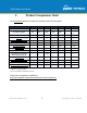
3 Product Comparison Chart Click underlined features to reach the relevant portion of the manual.
MFA MFA MFA 200 500 750 12 2 5 7 5Gbp s 8Gbp s 200 800 1.5G bps - - - - - - Yes Yes Yes Yes Yes Yes Yes SpeedFusion Hot Failover Yes Yes Yes Yes -^ Yes Yes SF Bandwidth Bonding Yes Yes Yes Yes -^ Yes Yes SF WAN Smoothing Yes Yes Yes Yes -^ Yes Yes Drop-In Mode Yes Yes Yes Yes Yes Yes Yes High Availability Yes Yes Yes Yes Yes Yes Yes Simultaneous Dual-Band 802.
4 Product Features Peplink Balance Series products enable all LAN users to share broadband Internet connections and provide advanced features to enhance Internet access. The following is a list of supported features: 4.1 Supported Network Features 4.1.
● ● IPsec VPN for network-to-network connections (works with Cisco and Juniper only) L2TP / PPTP and IPsec passthrough 4.1.4 Inbound Traffic Management ● ● TCP/UDP traffic redirection to dedicated LAN server(s) Inbound link load balancing by means of DNS 4.1.
4.
5 5.1 Advanced Feature Summary Drop-in Mode and LAN Bypass: Transparent Deployment As your organization grows, it needs more bandwidth. But modifying your network would require effort better spent elsewhere. In Drop-in Mode, you can conveniently install your Peplink router without making any changes to your network. And if the Peplink router loses power for any reason, LAN Bypass will safely and automatically bypass the Peplink router to resume your original network connection. http://www.peplink.
5.2 QoS: Clearer VoIP VoIP and videoconferencing are highly sensitive to latency. With QoS, Peplink routers can detect VoIP traffic and assign it the highest priority, giving you crystal-clear calls. 5.3 Per-User Bandwidth Control http://www.peplink.
With per-user bandwidth control, you can define bandwidth control policies for up to 3 groups of users to prevent network congestion. Define groups by IP address and subnet, and set bandwidth limits for every user in the group. 5.4 High Availability via VRRP When your organization has a corporate requirement demanding the highest availability with no single point of failure, you can deploy two Peplink routers in High Availability mode.
5.5 USB Modem and Android Tethering For increased WAN diversity, plug in a USB LTE modem as backup. Peplink routers are compatible with over 200 modem types. You can also tether to smartphones running Android 4.1.X and above. 5.6 Built-In Remote User VPN Support http://www.peplink.
Use L2TP with IPsec to safely and conveniently connect remote clients to your private network. L2TP with IPsec is supported by most devices, but legacy devices can also connect using PPTP. Click here for full instructions on setting up L2TP with IPsec. 5.7 LACP NIC Bonding Use 802.3ad to combine multiple LAN connections into a virtual LAN connection. This virtual connection has higher throughput and redundancy in case any single link fails. http://www.peplink.
6 Package Contents The contents of Peplink Balance product packages are as follows: 6.1 ● ● ● Peplink Balance One Power adapter Information slip 6.2 ● ● ● Peplink MediaFast 200 Peplink MediaFast 200 Power adapter Information slip 6.6 ● ● ● ● Peplink Balance 305/380/580/710/1350/2500 Peplink Balance 305/380/580/710/1350/2500 Power cord Information slip Rackmount kit 6.5 ● ● ● Peplink Balance 210/310 Peplink Balance 210/310 Power adapter Information slip Rackmount kit 6.
7 7.1 Peplink Balance Overview Peplink Balance One 7.1.1 Panel Appearance 7.1.2 LED Indicators The statuses indicated by the front panel LEDs are as follows: Power and Status Indicators Wi-Fi OFF – Wi-Fi is off Green – Ready OFF – Upgrading firmware Status Red – Booting up or busy Blinking red – Boot up error Green – Ready LAN and WAN Ports http://www.peplink.
Green LED ON – 10 / 100 / 1000 Mbps Blinking – Data is transferring Orange LED OFF – No data is being transferred or port is not connected Port Type Auto MDI/MDI-X ports USB Port USB Ports 7.2 For future functionality Peplink Balance 20 7.2.1 Panel Appearance 7.2.2 LED Indicators The statuses indicated by the front panel LEDs are as follows: Power and Status Indicators Power OFF – Power off http://www.peplink.
Green – Power on OFF – Upgrading firmware Red – Booting up or busy Status Blinking red – Boot up error Green – Ready LAN and WAN Ports Green LED Orange LED Port Type ON – 10 / 100 / 1000 Mbps Blinking – Data is transferring OFF – No data is being transferred or port is not connected Auto MDI/MDI-X ports USB Port USB Ports 7.3 For connecting a 4G/3G USB modem Peplink Balance 30 LTE 7.3.1 Panel Appearance http://www.peplink.
7.3.2 LED Indicators The statuses indicated by the front panel LEDs are as follows: Power and Status Indicators Power OFF – Power off Green – Power on OFF – Upgrading firmware Status Red – Booting up or busy Blinking red – Boot up error Green – Ready LAN and WAN Ports Green LED Orange LED Port Type ON – 10 / 100 /1000 Mbps Blinking – Data is transferring OFF – No data is being transferred or port is not connected Auto MDI/MDI-X ports http://www.peplink.
USB Port USB Ports 7.4 For connecting a 4G/3G USB modem Peplink Balance 50 7.4.1 Front Panel Appearance 7.4.2 LED Indicators The statuses indicated by the front panel LEDs are as follows: Power and Status Indicators Power OFF – Power off Green – Power on OFF – Upgrading firmware Status Red – Booting up or busy Blinking red – Boot up error http://www.peplink.
Green – Ready LAN and WAN Ports Green LED Orange LED Port Type ON – 10 / 100 /1000 Mbps Blinking – Data is transferring OFF – No data is being transferred or port is not connected Auto MDI/MDI-X ports USB Port USB Ports 7.5 For connecting a 4G/3G USB modem Peplink Balance 210 7.5.1 Front Panel Appearance http://www.peplink.
7.5.2 LED Indicators The statuses indicated by the front panel LEDs are as follows: Power and Status Indicators OFF – Upgrading firmware Red – Booting up or busy Status Blinking red – Boot up error Green – Ready LAN and WAN Ports Green LED Orange LED Port Type ON – 10 / 100 / 1000 Mbps Blinking – Data is transferring OFF – No data is being transferred or port is not connected Auto MDI/MDI-X ports USB Port USB Ports 7.6 For connecting a 4G/3G USB modem Peplink Balance 310 7.6.
7.6.2 LED Indicators The statuses indicated by the front panel LEDs are as follows: Power and Status Indicators OFF – Upgrading firmware Status Red – Booting up or busy Blinking red – Boot up error Green – Ready LAN and WAN Ports Green LED Orange LED Port Type ON – 10 / 100 / 1000 Mbps Blinking – Data is transferring OFF – No data is being transferred or port is not connected Auto MDI/MDI-X ports http://www.peplink.
USB Port USB Ports 7.7 For connecting a 4G/3G USB modem Peplink Balance 305 7.7.1 Front Panel Appearance 7.7.2 LED Indicators The statuses indicated by the front panel LEDs are as follows: Power and Status Indicators Power LED OFF – Power off GREEN – Power on LAN Port, WAN 1 – 3 Ports ORANGE – 1000 Mbps Right LED GREEN – 100 Mbps OFF – 10 Mbps http://www.peplink.
Solid – Port is connected without traffic Left LED Blinking – Data is transferring OFF – Port is not connected Port Type Auto MDI/MDI-X ports Console and USB Ports Console Port USB Ports Reserved for engineering use For connecting a 4G/3G USB modem http://www.peplink.
7.8 Peplink Balance 380 7.8.1 Panel Appearance 7.8.2 LED Indicators The statuses indicated by the front panel LEDs are as follows: Power and Status Indicators Power LED OFF – Power off GREEN – Power on LAN Port, WAN 1 – 3 Ports ORANGE – 1000 Mbps Right LED GREEN – 100 Mbps OFF – 10 Mbps Left LED Solid – Port is connected without traffic Blinking – Data is transferring http://www.peplink.
OFF – Port is not connected Port Type Auto MDI/MDI-X ports Console and USB Ports Console Port USB Ports 7.9 Reserved for engineering use For connecting a 4G/3G USB modem Peplink Balance 580 7.9.1 Panel Appearance 7.9.2 LED Indicators The statuses indicated by the front panel LEDs are as follows: Power and Status Indicators Power LED OFF – Power off GREEN – Power on LAN Port, WAN 1 – 5 Ports Right LED ORANGE – 1000 Mbps http://www.peplink.
GREEN – 100 Mbps OFF – 10 Mbps Solid – Port is connected without traffic Left LED Blinking – Data is transferring OFF – Port is not connected Port Type Auto MDI/MDI-X ports Console and USB Ports Console Port USB Ports Reserved for engineering use For connecting a 4G/3G USB modem 7.10 Peplink Balance 710 7.10.1 Front Panel Appearance 7.10.2 LED Indicators Status indicated in the front panel is as follows: http://www.peplink.
LED Indicator Power LED OFF – Power off GREEN – Power on LAN Port, WAN 1 – 7 Ports Green LED ON – 1000 Mbps OFF – 100/10 Mbps Solid – Port is connected without traffic Orange LED Blinking – Data is transferring OFF – Port is not connected Port Type Auto MDI/MDI-X ports Console & USB Ports Console Port USB Ports Reserved for engineering use For connecting a 4G/3G USB modem 7.11 Peplink Balance 1350 7.11.1 Panel Appearance http://www.peplink.
7.11.2 LED Indicators Status indicated in the front panel is as follows: LED Indicator Power LED OFF – Power off GREEN – Power on LAN Port, WAN 1 – 13 Ports ORANGE – 1000 Mbps Right LED GREEN – 100 Mbps OFF – 10 Mbps Solid – Port is connected without traffic Left LED Blinking – Data is transferring OFF – Port is not connected Port Type Auto MDI/MDI-X ports Console & USB Ports http://www.peplink.
Console Port USB Ports Reserved for engineering use For connecting a 4G/3G USB modem 7.12 Peplink Balance 2500 7.12.1 Panel Appearance 7.12.2 LED Indicators Status indicated in the front panel is as follows: LED Indicator Power LED OFF – Power off GREEN – Power on LAN and WAN Ports http://www.peplink.
ORANGE – 1000 Mbps Right LED GREEN – 100 Mbps OFF – 10 Mbps Solid – Port is connected without traffic Left LED Blinking – Data is transferring OFF – Port is not connected Port Type Auto MDI/MDI-X ports Console & USB Ports Console Port USB Ports Reserved for engineering use For connecting a 4G/3G USB modem 8 Peplink MediaFast Overview 8.1 Peplink MediaFast 200 8.1.1 Panel Appearance http://www.peplink.
8.1.2 LED Indicators Status indicated in the front panel is as follows: LED Indicator OFF – Power off Power LED GREEN – Power on LAN 1-3 Ports, WAN 1-5 Ports ORANGE – 1000 Mbps Right LED GREEN – 100 Mbps OFF – 10 Mbps Solid – Port is connected without traffic Left LED Blinking – Data is transferring OFF – Port is not connected Port Type Auto MDI/MDI-X ports Console & USB Ports Console Port USB Ports 8.2 Reserved for engineering use For connecting 4G/3G USB modems Peplink MediaFast 500 8.2.
8.2.2 LED Indicators Status indicated in the front panel is as follows: LED Indicator Power LED OFF – Power off GREEN – Power on LAN 1-3 Ports, WAN 1-5 Ports ORANGE – 1000 Mbps Right LED GREEN – 100 Mbps OFF – 10 Mbps Solid – Port is connected without traffic Left LED Blinking – Data is transferring OFF – Port is not connected Port Type Auto MDI/MDI-X ports Console & USB Ports Console Port Reserved for engineering use http://www.peplink.
USB Ports 8.3 For connecting 4G/3G USB modems Peplink MediaFast 750 8.3.1 Panel Appearance 8.3.2 LED Indicators Status indicated in the front panel is as follows: LED Indicator Power LED OFF – Power off GREEN – Power on LAN 1-3 Ports, WAN 1-5 Ports ORANGE – 1000 Mbps Right LED GREEN – 100 Mbps OFF – 10 Mbps Solid – Port is connected without traffic Left LED Blinking – Data is transferring OFF – Port is not connected Port Type Auto MDI/MDI-X ports http://www.peplink.
Console & USB Ports Console Port USB Ports Reserved for engineering use For connecting 4G/3G USB modems http://www.peplink.
9 LCD Display Menu > HA State: Master/Slave > LAN IP > VIP > System Status > System > Firmware ver.
10 Installation The following section details connecting the Peplink Balance to your network: 10.
(This is the default LAN IP address of the Peplink Balance.) Enter the following to access the web admin interface. Username: admin Password: admin 3. (This is the default admin user login of the Peplink Balance. The admin and read-only user password can be changed at System>Admin Security.) After successful login, the Dashboard of the web admin interface will be displayed. It looks similar to the following: http://www.peplink.
Important Note The Save button causes the changes to be saved. Configuration changes (e.g., WAN, LAN, admin settings, etc.) take effect after clicking the Apply Changes button on each page’s top-right corner. 11.2 Configuration with the Setup Wizard The Setup Wizard simplifies the task of configuring WAN connection(s) by guiding the configuration process step-by-step. To begin, click Setup Wizard after connecting to the web admin interface. Click Next >> to begin.
Click on the appropriate checkbox(es) to select the WAN connection(s) to be configured. If you have chosen to configure drop-in mode using the Setup Wizard, the WAN port to be configured in drop-in mode will be checked by default. If drop-in mode is going to be configured, the setup wizard will move on to Drop-in Settings. http://www.peplink.
If you are not using drop-in mode, select the connection method for the WAN connection(s) from the following screen: Depending on the selection of connection type, further configuration may be needed. For example, PPPoE and static IP require additional settings for the selected WAN port. Please refer to Section 13, Configuring the WAN Interface(s) for details on setting up DHCP, static IP, and PPPoE. If Mobile Internet Connection is checked, the setup wizard will move on to Operator Settings.
not selected in this step will be used as backup only. Click Next >> to continue. Choose the time zone of your country/region. Check the box Show all to display all time zone options. Check in the following screen to make sure all settings have been configured correctly, and then click Save Settings to confirm. After finishing the last step in the setup wizard, click Apply Changes on the page header to allow the configuration changes to take effect. http://www.peplink.
12 Network Tab 12.1 WAN From Network>WAN, choose a WAN connection by clicking it. You can also enable IPv6 support in this section WAN Connection Settings (Ethernet) Clicking an Ethernet WAN connection will result in the following screen: WAN Connection Settings WAN Connection Name Enable Enter a name to represent this WAN connection. This setting enables the WAN connection. If schedules have been defined, you will be able to select a schedule to apply to the connection. http://www.peplink.
There are three possible connection methods for Ethernet WAN: Connection Method Routing Mode ● ● ● DHCP Static IP PPPoE The connection method and details are determined by, and can be obtained from, the ISP. See the following sections for details on each connection method. DNS server settings can be configured in the corresponding menu for each connection method. This field shows that NAT (network address translation) will be applied to the traffic routed over this WAN connection.
Connection Settings WAN Connection Name Enable Routing Mode Indicate a name you wish to give this WAN connection Click the checkbox to toggle the on and off state of this connection. This option allows you to select the routing method to be used in routing IP frames via the WAN connection. The mode can be either NAT (Network Address Translation) or IP Forwarding. In the case if you need to choose IP Forwarding for your scenario. Click the enable IP Forwarding.
Each ISP may provide a set of DNS servers for DNS lookups. This setting specifies the DNS (Domain Name System) servers to be used when a DNS lookup is routed through this connection. DNS Servers Selecting Obtain DNS server address automatically results in the DNS servers assigned by the WAN DHCP server being used for outbound DNS lookups over the connection. (The DNS servers are obtained along with the WAN IP address assigned by the DHCP server.
provider’s data roaming policy before proceeding. This setting applies to 3G/EDGE/GPRS modems only. It does not apply to EVDO/EVDO Rev. A modems. This allows you to configure the APN settings of your connection. If Auto is selected, the mobile operator should be detected automatically. The connected device will be configured and connection will be made automatically.
When a static speed is set, you may choose whether to advertise its speed to the peer device or not. Advertise Speed is selected by default. You can choose not to advertise the port speed if the port has difficulty in negotiating with the peer device. Default: Auto MTU This field is for specifying the Maximum Transmission Unit value of the WAN connection. An excessive MTU value can cause file downloads stall shortly after connected. You may consult your ISP for the connection's MTU value.
this connection. Selecting Obtain DNS server address automatically results in the DNS servers assigned by the WAN DHCP server being used for outbound DNS lookups over the connection. (The DNS servers are obtained along with the WAN IP address assigned by the DHCP server.) When Use the following DNS server address(es) is selected, you may enter custom DNS server addresses for this WAN connection into the DNS server 1 and DNS server 2 fields.
ICMP ping packets will be issued to test the connectivity with a configurable target IP address or hostname. A WAN connection is considered as up if ping responses are received from either one or both of the ping hosts. PING Hosts This setting specifies IP addresses or hostnames with which connectivity is to be tested via ICMP ping. If Use first two DNS servers as Ping Hosts is checked, the target ping host will be the first DNS server for the corresponding WAN connection.
HTTP connections will be issued to test connectivity with configurable URLs and strings to match. URL1 WAN Settings>WAN Edit>Health Check Settings>URL1 The URL will be retrieved when performing an HTTP health check. When String to Match is left blank, a health check will pass if the HTTP return code is between 200 and 299 (Note: HTTP redirection codes 301 or 302 are treated as failures).
Other Health Check Settings Timeout This setting specifies the timeout in seconds for ping/DNS lookup requests. The default timeout is 5 seconds. Health Check Interval This setting specifies the time interval in seconds between ping or DNS lookup requests. The default health check interval is 5 seconds. Health Check Retries This setting specifies the number of consecutive ping/DNS lookup timeouts after which the Peplink Balance will treat the corresponding WAN connection as down.
Bandwidth Allowance Monitor Settings Bandwidth Allowance Monitor Action Start Day Monthly Allowance If Email Notification is enabled, you will be notified by email when usage hits 75% and 95% of the monthly allowance. If Disconnect when usage hits 100% of monthly allowance is checked, this WAN connection will be disconnected automatically when the usage hits the monthly allowance.
Additional Public IP Settings IP Address List IP Address List represents the list of fixed Internet IP addresses assigned by the ISP in the event that more than one Internet IP address is assigned to this WAN connection. Enter the fixed Internet IP addresses and the corresponding subnet mask, and then click the Down Arrow button to populate IP address entries to the IP Address List. Dynamic DNS Settings The Peplink Balance allows registering domain name relationships to dynamic DNS service providers.
Dynamic DNS Settings Service Provider This setting specifies the dynamic DNS service provider to be used for the WAN. Supported providers are: ● changeip.com ● dyndns.org ● no-ip.org ● tzo.com ● DNS-O-Matic ● Others… support custom Dynamic DNS servers by entering its URL. Works with any service compatible with DynDNS API. Select Disabled to disable this feature.
has not been not updated for a long time. Therefore, the Peplink Balance performs an update every 23 days, even if a WAN’s IP address did not change. 12.2 LAN 12.2.1 Network Settings (Without VLAN) By default, LAN is configured without VLAN functionality enabled. To Enable VLAN, click the , icon on the right of the IP Settings menu. Begin setting up your physical LAN by entering IP settings (VLAN configuration will be covered following physical LAN setup).
Enable drop-in mode using the Setup Wizard. After enabling this feature and selecting the WAN for drop-in mode, various settings, including the WAN's connection method and IP address, will be automatically updated. When drop-in mode is enabled, the LAN and the WAN for drop-in mode ports will be bridged. Traffic between the LAN hosts and WAN router will be forwarded between the devices. In this case, the hosts on both sides will not notice any IP or MAC address changes.
WAN for DropIn Mode Select the WAN port to be used for drop-in mode. If WAN 1 with LAN Bypass is selected, the high availability feature will be disabled automatically. Shared Drop-In IPA When this option is enabled, the passthrough IP address will be used to connect to WAN hosts (email notification, remote syslog, etc.). The Balance will listen for this IP address when WAN hosts access services provided by the Balance (web admin access from the WAN, DNS server requests, etc.).
IP Settings IP Address & Subnet Mask Enter the Peplink Balance’s IP address and subnet mask values to be used on the LAN. To enable multiple VLANs, press the button on the top right-hand corner. Network Settings Name VLAN ID Inter-VLAN routing Captive Portal Enter a name for the LAN. Enter a VLAN ID for your LAN. Check this box to enable routing between virtual LANs. Check this box to turn on captive portals.
Network IsolationA Spanning Tree ProtocolA When Layer 2 bridging is enabled, this field specifies the port to be bridged to the remote site. If you choose WAN, the selected WAN will be dedicated to bridging with the remote site and will be disabled for WAN purposes. The LAN port will remain unchanged. Override IP Address when bridge is connectedA Select "Do not override" if the LAN IP address and local DHCP server should remain unchanged after the Layer 2 PepVPN is up.
DHCP Server Logging Check this box to log DHCP server activity. IP Range & Subnet Mask These settings allocate a range of IP addresses that will be assigned to LAN computers by the Peplink Balance’s DHCP server. Lease Time This setting specifies the length of time throughout which an IP address of a DHCP client remains valid. Upon expiration of Lease Time, the assigned IP address will no longer be valid and the IP address assignment must be renewed.
DHCP Relay Settings DHCP Relay Enter the address of the DHCP server here. DHCP requests will be relayed to it. DHCP Server IP Address DHCP requests from the LAN are relayed to the entered DHCP server. For active-passive DHCP server configurations, enter active and passive DHCP server IPs into the DHCP Server 1 and DHCP Server 2 fields. DHCP Option 82 This feature includes device information as relay agent for the attached client when forwarding DHCP requests from a DHCP client to a DHCP server.
Enter any needed DNS proxy settings. Once all settings have been entered, click Save to store your changes. DNS Proxy Settings Enable To enable the DNS proxy feature, check this box, and then set up the feature at Network>LAN>DNS Proxy Settings. A DNS proxy server can be enabled to serve DNS requests originating from LAN/PPTP/SpeedFusionTM peers. Requests are forwarded to the DNS servers/resolvers defined for each WAN connection.
Domain Lookup Policy DNS ResolversA A DNS proxy will look up the domain names defined here using only the specified connections. Check the box to enable the WINS server. A list of WINS clients will be displayed at Network>LAN>DNS Proxy Settings>DNS Resolvers. This field specifies which DNS resolvers will receive forwarded DNS requests. If no WAN/VPN/LAN DNS resolver is selected, all of the WAN’s DNS resolvers will be selected.
On this screen, you can enable specific ports, as well as determine the speed of the LAN ports, whether each port is a trunk or access port, can well as which VLAN each link belongs to, if any. 12.3 VPN 12.3.1 SpeedFusion Peplink Balance SpeedFusionTM Bandwidth Bonding is our patented technology that enables our SD-WAN routers to bond multiple Internet connections to increase site-to-site bandwidth and reliability.
SpeedFusion Profiles This table displays all defined profiles. Click the New Profile button to create a new profile for making a VPN connection to a remote unit via available WAN connections. Each pair of VPN connection requires its own profile. The local LAN subnet and subnets behind the LAN (defined under Static Route on the LAN Settings page) will be advertised to the VPN. All VPN members will be able to route to local subnets.
Link Failure Detection The bonded VPN can detect routing failures on the path between two sites over each WAN connection. Failed WAN connections will not be used to route VPN traffic. Health check packets are sent to the remote unit to detect any failure. The more frequently checks are sent, the shorter the detection time, although more bandwidth will be consumed. When Recommended (default) is selected, a health check packet is sent every five seconds, and the expected detection time is 15 seconds.
A list of defined SpeedFusion connection profiles and a Link Failure Detection Time option will be shown. Click the New Profile button to create a new VPN connection profile for making a VPN connection to a remote Peplink Balance via the available WAN connections. Each profile is for making a VPN connection with one remote Peplink Balance. PepVPN Profile Settings Name This field is for specifying a name to represent this profile.
Remote ID / Pre-shared Key This optional field becomes available when Remote ID / Pre-shared Key is selected as the Peplink Balance’s VPN Authentication method, as explained above. Pre-shared Key defines the pre-shared key used for this particular VPN connection. The VPN connection's session key will be further protected by the pre-shared key. The connection will be up only if the pre-shared keys on each side match. When the peer is running firmware 5.0+, this setting will be ignored.
WAN's available bandwidth. Off - Disable WAN Smoothing. Normal - The total bandwidth consumption will be at most 2x of the original data traffic. Medium - The total bandwidth consumption will be at most 3x of the original data traffic. High - The total bandwidth consumption depends on the number of connected active tunnels. A - Advanced feature, please click the button on the top right-hand corner to activate.
problems (e.g.,unplugged cables or ISP problems) cause WAN1 to go down, our IPsec implementation will make use of WAN2 and WAN3 for failover. 12.3.2 IPsec VPN All Peplink products can make multiple IPsec VPN connections with Peplink routers, as well as Cisco and Juniper routers. Note that all LAN subnets and the subnets behind them must be unique. Otherwise, VPN members will not be able to access each other.
http://www.peplink.
IPsec VPN Settings Name This field is for specifying a local name to represent this connection profile. Active When this box is checked, this IPsec VPN connection profile will be enabled. Otherwise, it will be disabled. Connect Upon Disconnection of Check this box and select a WAN to connect to this VPN automatically when the specified Remote Gateway IP Address / Host Name WAN is disconnected. To activate this function, click the option.
Encapsulation Pre-shared Key This defines the peer authentication pre-shared key used to authenticate this VPN connection. The connection will be up only if the pre-shared keys on each side match. Remote Certificate (pem encoded) Available only when X.509 Certificate is chosen as the Authentication method, this field allows you to paste a valid X.509 certificate. Local ID In Main Mode, this field can be left blank.
12.4 Outbound Policy Outbound policies for managing and load balancing outbound traffic are located at Network>Outbound Policy. Click the button beside the Outbound Policy box: A selection menu will appear, giving you the choice between three different Outbound Policy Settings: Outbound Policy Settings High Application Compatibility Outbound traffic from a source LAN device is routed through the same WAN connection regardless of the destination Internet IP address and protocol.
the Service heading, click Default to change these settings. To rearrange the priority of outbound rules, drag and drop them into the desired sequence. By default, Auto is selected as the Default Rule. You can select Custom to change the algorithm to be used. Please refer to the upcoming sections for the details on the available algorithms. To create a custom rule, click Add Rule at the bottom of the table. Note that some Pepwave routers display this button at Advanced>PepVPN>PepVPN Outbound Custom Rules.
New Custom Rule Settings Service Name Enable This setting specifies the name of the outbound traffic rule. This setting specifies whether the outbound traffic rule takes effect. When Enable is checked, the rule takes effect: traffic is matched and actions are taken by the Pepwave router based on the other parameters of the rule. When Enable is unchecked, the rule does not take effect: the Pepwave router disregards the other parameters of the rule.
NOTE: if a server has one Internet IP address and multiple server names, and if one of the names is defined here, accesses to any one of the server names will also match this rule. Protocol and Port This setting specifies the IP protocol and port of traffic that matches this rule. Algorithm This setting specifies the behavior of the Pepwave router for the custom rule.
To define a new server, click Add Server, which displays the following screen: Enter a valid server name and its corresponding LAN IP address. Upon clicking Save after entering required information, the following screen appears. To define additional servers, click Add Server and repeat the above steps. 12.5.2 Services Services are defined at Network>Inbound Access>Services. Tip At least one server must be defined before services can be added.
Services Settings Enable Service Name IP Protocol This setting specifies whether the inbound service rule takes effect. When Yes is selected, the inbound service rule takes effect. If the inbound traffic matches the specified IP protocol and port, action will be taken by the Peplink Balance based on the other parameters of the rule. When No is selected, the inbound service rule does not take effect. The Peplink Balance will disregard the other parameters of the rule.
For example, if IP Protocol is set to TCP, Port is set to Single Port, and Service Port is set to 80, then TCP traffic received on Port 80 will be forwarded to the configured servers via port 80. Port Range: traffic that is received by the Peplink Balance via the specified protocol at the specified port range is forwarded via the same respective ports to the LAN hosts specified by the Servers setting.
When the options are enabled, a table listing all the forwarded ports under these two protocols can be found at Network>Services>UPnP / NAT-PMP. 12.5.3 DNS Settings The built-in DNS server functionality of the Peplink Balance facilitates inbound load balancing. With this functionality, NS/SOA DNS records for a domain name can be delegated to the Internet IP address(es) of the Peplink Balance.
DNS Servers This setting specifies the WAN IP addresses on which the DNS server of the Peplink Balance should listen. If no addresses are selected, the inbound link load balancing feature will be disabled and the Peplink Balance will not respond to DNS requests.
This page is for defining the domain’s SOA, NS, MX, CNAME, A, TXT, and SRV records. Seven tables are presented in this page for defining the five types of records. http://www.peplink.
12.5.3.1 SOA Records Click on the icon to choose whether to use the pre-defined default SOA record and NS records. If the option Use Default SOA and NS Records is selected, any changes made in the default SOA/NS records will be applied to this domain automatically. Otherwise, select the option Customize SOA Record for this domain to customize this domain's SOA and NS records. This table displays the current SOA record.
● ● ● ● ● ● domain, this field's value should be the WAN connection's name server IP address that is registered in the DNS registrar. If this field is entered, a corresponding A record for the name server will be created automatically. If it is left blank, the A record for the name server must be created manually. E-mail: Defines the e-mail address of the person responsible for this zone. Note: format should be mailbox-name.domain.com, e.g., hostmaster.example.com.
MX Records button in the MX Records box. Then the table will expand to look like the following: When creating an MX record for the domain itself (not a sub-domain), the Host field should be left blank. For each record, Priority and Mail Server name must be entered. Priority typically ranges from 10 to 100. Smaller numbers have a higher a priority. After finishing adding MX records, click the Save button. 12.5.3.4 CNAME Records The CNAME Record table shows the domain’s CNAME records.
12.5.3.5 A Records This table shows the A records of the domain name. To add an A record, click the New A Record button. The following screen will appear: A record may be automatically added for the SOA records with a name server IP address provided. A Record Host Name This field specifies the A record of this sub-domain to be served by the Peplink Balance. The wildcard character “*” is supported. The IP addresses of “*.domain.name" will be returned for every name ending with ".domain.
TTL This setting specifies the time to live of this record in external DNS caches. In order to reflect any dynamic changes on the IP addresses in case of link failure and recovery, this value should be set to a smaller value, e.g., 5 secs, 60 secs, etc. Priority This option specifies the priority of different connections. Select the Default option to apply the Default Connection Priority (refer to the table shown on the main DNS settings page) to an A record.
To add a new TXT record, click the New TXT Record button in the TXT Records box. Click the Edit button to edit the record. The time-to-live value and the TXT record’s value can be entered. Click the Save button to finish. When creating a TXT record for the domain itself (not a sub-domain), the Host field should be left blank. The maximum size of the TXT Value is 255 bytes. After editing the five types of records, you can leave the page by simply going to another section of the web admin interface. 12.5.3.
Reverse Lookup Zones Reverse lookup zones can be configured in Network>Inbound Access>DNS Settings. Reverse lookup refers to performing a DNS query to find one or more DNS names associated with a given IP address. The DNS stores IP addresses in the form of specially formatted names as pointer (PTR) records using special domains/zones. The zone is in-addr.arpa.
SOA Record You can click the link Click here to define SOA record to create or click on the Name Server field to edit the SOA record. Name Server: Enter the NS record's FQDN server name here. http://www.peplink.
For example: "ns1.mydomain.com" (equivalent to "www.1stdomain.com.") "ns2.mydomain.com." Email, Refresh, Retry, Expire, Min Time, and TTL are entered in the same way as in the forward zone. Please refer to Section 17.3.5 for details. NS Records The NS record of the name server defined in the SOA record is automatically added here. To create a new NS record, click the New NS Records button.
PTR Records To create a new PTR record, click the New PTR Record button. For Host IP Number field, enter the last integer in the IP address of a PTR record. For example. for the IP address 11.22.33.44, where the reverse lookup zone is 33.22.11.in-arpa.addr, the Host IP Number should be 44. The Points To field defines the host name which the PTR record should be pointed to. It must be a FQDN.
● ● ● In the Target DNS Server IP Address field, enter the IP address of the DNS server. In the Transfer via…field, choose the connection which you would like to transfer through. Select Next >> to continue. http://www.peplink.
● ● In the blank space, enter the Domain Names (Zones) which you would like to assign the IP address entered in the previous step. Enter one domain name per line. Select Next >> to continue. Important Note If you have entered domain(s) which already exist in your settings, a warning message will appear. Select Next >> to overwrite the existing record or << Back to go back to the previous step. http://www.peplink.
http://www.peplink.
After the zone records process have been fetched, the fetch results would be shown as above. You can view import details by clicking the corresponding hyperlink on the right-hand side. 12.6 NAT Mappings The Peplink Balance allows the IP address mapping of all inbound and outbound NAT’ed traffic to and from an internal client IP address. NAT mappings can be configured at Network>NAT Mappings. To add a rule for NAT mappings, click Add NAT Rule and the following screen will be displayed: http://www.peplink.
NAT Mapping Settings LAN Client(s) NAT Mapping rules can be defined for a single LAN IP Address, an IP Range, or an IP Network. http://www.peplink.
Address This refers to the LAN host’s private IP address. The system maps this address to a number of public IP addresses (specified below) in order to facilitate inbound and outbound traffic. This option is only available when IP Address is selected. Range The IP range is a contiguous group of private IP addresses used by the LAN host. The system maps these addresses to a number of public IP addresses (specified below) to facilitate outbound traffic.
Setting Up MediaFast Content Caching To access MediaFast content caching settings, select Network > MediaFast. MediaFast Enable Domains / IP Addresses Click the checkbox to enable MediaFast content caching. Choose to Cache on all domains, or enter domain names and then choose either Whitelist (cache the specified domains only) or Blacklist (do not cache the specified domains).
Cache Control Content Type Check these boxes to cache the listed content types or leave boxes unchecked to disable caching for the listed types. Cache Lifetime Settings Enter a file extension, such as JPG or DOC. Then enter a lifetime in days to specify how long files with that extension will be cached. Add or delete entries using the controls on the right. Viewing MediaFast Statistics To get details on storage and bandwidth usage, select Status>MediaFast. http://www.peplink.
12.7.1 Prefetch Schedule Content prefetching allows you to download content on a schedule that you define, which can help to preserve network bandwidth during busy times and keep costs down. To access MediaFast content prefetching settings, select Network > MediaFast > Prefetch Schedule. http://www.peplink.
Prefetch Schedule Settings Name This field displays the name given to the scheduled download. Status Check the status of your scheduled download here. Next Run Time/Last Run Time These fields display the date and time of the next and most recent occurrences of the scheduled download. Last Duration Check this field to ensure that the most recent download took as long as expected to complete.
Simply provide the requested information to create your schedule. Clear Web Cache Clear Statistics Click to clear all cached contentn. Note that this action cannot be undone. Click to clear all prefetch and status page statistics. 12.8 ContentHub Integrated into MediaFast-enabled routers, ContentHub allows you to deliver webpages and applications using the cache. To access ContentHub, navigate to Network > ContentHub: Check the Enable box.
The Active checkbox toggles the activation of the website/application. This will be useful when there are multiple applications being delivered. For type, you can select either Website or Application: Selecting Website: Domain/Path Both domain and path must be specified for website type. Source Enter the FTP server you will be downloading the content from. Enter your credentials under Username and Password.
Limit 12.9 MDM Settings In addition to performing content caching, MediaFast-enabled routers can also serve as an MDM, administrating to client devices. To access MDM Settings, navigate to Network > MDM Settings: MDM Settings Enable Account Settings Click this checkbox to enable MDM on your router. Click Follow Web Admin Account to allow client devices to use the built-in administrator account when performing MDM.
Captive Portal Settings Enable Hostname Access Mode Check Enable and then, optionally, select the LANs/VLANs that will use the captive portal. To customize the portal’s form submission and redirection URL, enter a new URL in this field. To reset the URL to factory settings, click Default. Click Open Access to allow clients to freely access your router. Click User Authentication to force your clients to authenticate before accessing your router. This authenticates your clients through a RADIUS server.
Fill in the necessary information to complete your connection to the server and enable authentication. Access Quota Quota Reset Time Allowed Networks Set a time and data cap to each user’s Internet usage. This menu determines how your usage quota resets. Setting it to Daily will reset it at a specified time every day. Setting a number of minutes after quota reached establish a timer for each user that begins after the quota has been reached.
The Portal Customization menu has two options: and . Clicking will result in a pop-up previewing the captive portal that your clients will see. Clicking will result in the appearance of following menu: Portal Customization Logo Image Click the Choose File button to select an logo to use for the built-in portal. Message If you have any additional messages for your users, enter them in this field.
Landing Page 12.11QoS 12.11.1 User Groups LAN and PPTP clients can be categorized into three user groups - Manager, Staff, and Guest. This menu allows you to define rules and assign client IP addresses or subnets to a user group. You can apply different bandwidth and traffic prioritization policies on each user group in the Bandwidth Control and Application sections. The table is automatically sorted, and the table order signifies the rules' precedence.
12.11.2 Bandwidth Control This section is to define how much minimum bandwidth will be reserved to each user group when a WAN connection is in full load. When this feature is enabled, a slider with two indicators will be shown. You can move the indicators to adjust each group's weighting. The lower part of the table shows the corresponding reserved download and uploads bandwidth value of each connection. By default, 50% of bandwidth has been reserved for Manager, 30% for Staff, and 20% for Guest.
Prioritization for Custom Application Click the Add button to define a custom application. Click the button in the Action column to delete the custom application in the corresponding row. When Supported Applications is selected, the Peplink Balance will inspect network traffic and prioritize the selected applications. Alternatively, you can select Custom Applications and define the application by providing the protocol, scope, port number, and DSCP value.
DSL/Cable Optimization DSL/cable-based WAN connections have lower upload bandwidth and higher download bandwidth. When a DSL/cable circuit's uplink is congested, the download bandwidth will be affected. Users will not be able to download data at full speed until the uplink becomes less congested. DSL/Cable Optimization can relieve such an issue. When it is enabled, the download speed will become less affected by the upload traffic. By default, this feature is enabled. 12.
The inbound firewall settings are located at Network>Firewall>Access Rules. Click Add Rule to display the following window: Inbound / Outbound Firewall Settings Rule Name This setting specifies a name for the firewall rule. http://www.peplink.
Enable This setting specifies whether the firewall rule should take effect. If the box is checked, the firewall rule takes effect. If the traffic matches the specified protocol/IP/port, actions will be taken by Peplink Balance based on the other parameters of the rule. If the box is not checked, the firewall rule does not take effect. The Peplink Balance will disregard the other parameters of the rule. Click the dropdown menu next to the checkbox to place this firewall rule on a time schedule.
Action This setting specifies the action to be taken by the router upon encountering traffic that matches the both of the following: ● Source IP & port ● Destination IP & port With the value of Allow for the Action setting, the matching traffic passes through the router (to be routed to the destination). If the value of the Action setting is set to Deny, the matching traffic does not pass through the router (and is discarded).
To change a rule’s priority, simply drag and drop the rule: ● Hold the left mouse button on the rule. ● Move it to the desired position. ● Drop it by releasing the mouse button. To remove a rule, click the button. Rules are matched from top to the bottom. If a connection matches any one of the upper rules, the matching process will stop. If none of the rules match the connection, the Default rule will be applied. The Default rule is Allow for both outbound and inbound access.
● ● o Xmas tree o Another Xmas tree o Null scan o SYN/RST o SYN/FIN SYN flood prevention Ping flood attack prevention 12.12.2 Content Blocking http://www.peplink.
http://www.peplink.
Application Blocking Choose applications to be blocked from LAN/PPTP/PepVPN peer clients' access, except for those on the Exempted User Groups or Exempted Subnets defined below. Web Blocking Defines web site domain names to be blocked from LAN/PPTP/PepVPN peer clients' access except for those on the Exempted User Groups or Exempted Subnets defined below. If "foobar.com" is entered, any web site with a host name ending in foobar.com will be blocked, e.g. www.foobar.com, foobar.com, etc. However, "myfoobar.
access blocking rules. URL Logging Click enable, and the enter the ip address and port (if applicable) where your remote syslog server is located. 12.13OSPF & RIPv2 The Peplink Balance supports OSPF and RIPv2 dynamic routing protocols. Click the Network tab from the top bar, and then click the OSPF & RIPv2 item on the sidebar to reach the following menu: OSPF Router ID Area This field determines the ID of the router. By default, this is specified as the LAN IP address.
OSPF Settings Area ID Link Type Authentication Interfaces Determine the name of your Area ID to apply to this group. Machines linked to this group will send and receive related OSPF packets, while unlinked machines will ignore it. Choose the network type that this area will use. Choose an authentication method, if one is used, from this drop-down menu. Available options are MD5 and Text. Enter the authentication key next to the drop-down menu.
To access RIPv2 settings, click . RIPv2 Settings Authentication Interfaces Choose an authentication method, if one is used, from this drop-down menu. Available options are MD5 and Text. Enter the authentication key next to the drop-down menu. Determine which interfaces this group will use to listen to and deliver RIPv2 packets. Route Advertisement Authentication Interfaces Choose an authentication method, if one is used, from this drop-down menu. Available options are MD5 and Text.
12.14Remote User Access Networks routed by a Peplink Balance can be remotely accessed via L2TP with IPsec or PPTP. To configure this feature, navigate to Network > Remote User Access Remote User Access Settings Enable Click the checkbox to enable Remote User Access. VPN Type Determine whether remote devices can connect to the Balance using L2TP with IPsec or PPTP. For greater security, we recommend you connect using L2TP with IPsec. Preshared Key Enter your preshared key in the text field.
Listen On User Accounts This setting is for specifying the WAN IP addresses where the PPTP server of the router should listen on. This setting allows you to define the PPTP User Accounts. Click Add to input username and password to create an account. After adding the user accounts, you can click on a username to edit the account password. Click the button X to delete the account in its corresponding row. Click the format. button to switch to enters user accounts by pasting the information in.CSV 12.
An elaboration on the technical details of the implementation of virtual router redundancy protocol (VRRP, RFC 3768) by the Balance follows: ● In an HA configuration, the two Peplink Balance units communicate with each other using VRRP over the LAN. ● The two Peplink Balance units broadcast heartbeat signals to the LAN at a frequency of one heartbeat signal per second.
the LAN IP Address and the Subnet Mask fields are set correctly in the LAN settings page. You can refer to the Event Log for the configuration synchronization status. Master Serial Number If Configuration Sync. is checked, the serial number of the master unit is required here for the feature to work properly. Virtual IP The HA pair must share the same Virtual IP. The Virtual IP and the LAN Administration IP must be under the same network.
Please note that the drop-in WAN cannot be configured as a LAN bypass port while it is configured for high availability. 12.15.2 Certificate Manager This section allows you to assign certificates for local VPN and web admin SSL. The local keys will not be transferred to another device by any means. 12.15.3 Service Forwarding Service forwarding settings are located at Network>Misc. Settings>Service Forwarding. http://www.peplink.
Service Forwarding SMTP Forwarding When this option is enabled, all outgoing SMTP connections destined for any host at TCP port 25 will be intercepted. These connections will be redirected to a specified SMTP server and port number. SMTP server settings for each WAN can be specified after selecting Enable. Web Proxy Forwarding When this option is enabled, all outgoing connections destined for the proxy server specified in Web Proxy Interception Settings will be intercepted.
SMTP Forwarding Some ISPs require their users to send e-mails via the ISP’s SMTP server. All outgoing SMTP connections are blocked except those connecting to the ISP’s. The Peplink Balance supports the interception and redirection of all outgoing SMTP connections (destined for TCP port 25) via a WAN connection to the WAN’s corresponding SMTP server. To enable the feature, select Enable under SMTP Forwarding Setup. Check Enable Forwarding for the WAN connection(s) that needs forwarding.
specified web proxy server and port number. Redirected server settings for each WAN can be set here. If forwarding is disabled for a WAN, then web proxy connections for that WAN will simply be forwarded to the connection’s original destination. DNS Forwarding When DNS forwarding is enabled, all clients’ outgoing DNS requests will also be intercepted and forwarded to the built-in DNS proxy server.
SIP Session initiation protocol, aka SIP, is a voice-over-IP protocol. The Peplink Balance can act as a SIP application layer gateway (ALG) which binds connections for the same SIP session to the same WAN connection and translate IP address in the SIP packets correctly in NAT mode. Such passthrough support is always enabled and there are two modes for selection: Standard Mode and Compatibility Mode.
AP Controller AP Management Support Remote AP Permitted AP 13.1.2 The AP controller for managing Pepwave APs can be enabled by checking this box. When this option is enabled, the AP controller will wait for management connections originating from APs over the LAN on TCP and UDP port 11753. It will also wait for captive portal connections on TCP port 443. An extended DHCP option, CAPWAP Access Controller addresses (field 138), will be added to the DHCP server.
defined and managed in this section. After defining a wireless network, users can choose the network in AP Profiles. Click the button New SSID to create a new network profile, or click the existing network profile to modify its settings. SSID Settings SSID This setting specifies the SSID of the virtual AP to be scanned by Wi-Fi clients. Enable Choose an operating schedule for this SSID.
IGMP Snooping A To allow the Peplink Balance to listen to internet group management protocol (IGMP) network traffic, select this option. DHCP Option 82 A If you use a distributed DHCP server/relay environment, you can enable this option to provide additional information on the manner in which clients are physically connected to the network.
When WPA/WPA2 - Enterprise is configured, RADIUS-based 802.1 x authentication is enabled. Under this configuration, the Shared Key option should be disabled. When using this method, select the appropriate version using the V1/V2 controls. The security level of this method is known to be very high. When WPA/WPA2- Personal is configured, a shared key is used for data encryption and authentication. When using this configuration, the Shared Key option should be enabled.
Guest Protect Block All Private IP Custom Subnet Block Exception Block PepVPN Check this box to deny all connection attempts by private IP addresses. To create a custom subnet for guest access, enter the IP address and choose a subnet mask from the drop-down menu. To add the new subnet, click click . . To delete a custom subnet, To block access from a particular subnet, enter the IP address and choose a subnet mask from the drop-down menu. To add the new subnet, click click . .
Client Upstream Limit Enter a value in kpbs to limit connected clients’ upstream bandwidth. Enter 0 to allow unlimited upstream bandwidth. Client Downstream Limit Enter a value in kpbs to limit connected clients’ downstream bandwidth. Enter 0 to allow unlimited downstream bandwidth. Max Number of Clients Enter the maximum number of clients that can simultaneously connect to the wireless network or enter 0 to allow an unlimited number of connections.
field to allow or block TCP or UDP traffic from that port only. You can also choose Port Range and enter a range of ports in the provided fields to allow or deny TCP or UDP traffic from the specified port range. IP Address / Subnet Mask If you have chosen IP Address as your firewall rule type, enter the IP address and subnet mask identifying the subnet to allow or deny. MAC Address If you have chosen MAC Address as your firewall rule type, enter the MAC address identifying the machine to allow or deny.
AP Settings (part 2) Protocol Channel Width Channel This option allows you to specify whether 802.11b and/or 802.11g client association requests will be accepted. Available options are 802.11ng and 802.11na. By default, 802.11ng is selected. Available options are 20 MHz, 40 MHz, and Auto (20/40 MHz) . Default is Auto (20/40 MHz), which allows both widths to be used simultaneously. This option allows you to select which 802.11 RF channel will be utilized. Channel 1 (2.412 GHz) is selected by default.
Advanced AP Settings Management VLAN ID Operating Schedule Beacon Rate A Beacon Interval A This field specifies the VLAN ID to tag to management traffic, such as communication traffic between the AP and the AP Controller. The value is zero by default, which means that no VLAN tagging will be applied. NOTE: Change this value with caution as alterations may result in loss of connection to the AP Controller. Choose from the schedules that you have defined in System>Schedule.
Slot Time A A This field is for specifying the unit wait time before transmitting a packet. By default, this field is set to 9 µs. ACK Timeout A This field is for setting the wait time to receive an acknowledgement packet before performing a retransmission. By default, this field is set to 48 µs. Frame Aggregation A This option allows you to enable frame aggregation to increase transmission throughput. - Advanced feature, please click the http://www.peplink.
Web Administration Settings Enable Ticking this box enables web admin access for APs located on the WAN. Web Access Protocol Determines whether the web admin portal can be accessed thorugh HTTP or HTTPS Management Port Determines the port at which the management UI can be accessed. Admin Username Determines the username to be used for logging into the web admin portal Admin Password Determines the password for the web admin portal on external AP. 13.2 AP Controller Status 13.2.
AP Controller License Limit This field displays the maximum number of AP your Balance router can control. You can purchase licenses to increase the number of AP you can manage. Frequency Underneath, there are two check boxes labeled 2.4 Ghz and 5 Ghz. Clicking either box will toggle the display of information for that frequency. By default, the graphs display the number of clients and data usage for both 2.4GHz and 5 GHz frequencies. SSID The colored boxes indicate the SSID to display information for.
13.2.2 Access Points (Usage) A detailed breakdown of data usage for each AP is available at AP> Access Point. Usage AP Name/Serial Number Online Status This field enables you to quickly find your device if you know its name or serial number. Fill in the field to begin searching. Partial names and serial numbers are supported. This button toggles whether your search will include offline devices.
Click the icon to configure each client For easier network management, you can give each client a name and designate its location. You can also designate which firmware pack (if any) this client will follow, as well as the channels on which the client will broadcast. Click the icon to see a graph displaying usage: Click any point in the graphs to display detailed usage and client information for that device, using that SSID, at that point in time.
Click the Event tab next to Wireless Usage to view a detailed event log for that particular device: 13.2.3 Wireless SSID In-depth SSID reports are available under AP > SSID. http://www.peplink.
Click the blue arrow on any SSID to obtain more detailed usage information on each SSID. 13.2.4 Wireless Client You can search for specific Wi-Fi users by navigating to AP > Wireless Client. Here, you will be able to see your network’s heaviest users as well as search for specific users. Click the icon to bookmark specific users, and click the icon for additional details about each user: http://www.peplink.
13.2.5 Nearby Device A listing of near devices can be accessed by navigating to AP > Controller Status > Nearby Device. http://www.peplink.
Nearby Devices Hovering over the device MAC address will result in a popup with information on how this device was detected. Click the icons and the device will be moved to the bottom table of identified devices. 13.2.6 Event Log You can access the AP Controller Event log by navigating to AP > Controller Status > Event Log. http://www.peplink.
Events This event log displays all activity on your AP network, down to the client level. Use to filter box to search by MAC address, SSID, AP Serial Number, or AP Profile name. Click View Alerts to see only alerts, and click the More… link for additional records. 13.3 Toolbox Additional tools for managing firmware packs, power adjustment, and channel assignment can be found at AP>Toolbox. Firmware Packs This is the first menu that will appear. Here, you can manage the firmware of your AP.
14 System Tab 14.1 System 14.1.1 Admin Security Admin Settings Router Name Admin User This field allows you to define a name for this Peplink Balance unit. By default, Router Name is set as Balance_XXXX, where XXXX refers to the last 4 digits of the serial number of that balance unit. Admin User Name is set as admin by default, but can be changed, if desired. http://www.peplink.
Name Admin Password This field allows you to specify a new administrator password. Confirm Admin Password This field allows you to verify and confirm the new administrator password. Read-only User Name Read-only User Name is set as user by default, but can be changed, if desired. User Password This field allows you to specify a new user password. Once the user password is set, the read-only user feature will be enabled.
Connection Restricted Admin Access CLI SSH & Console CLI SSH Port choose from LAN, WAN, and VPN connections. Check this box to restrict management to administrators connected to the management port. The CLI (command line interface) can be accessed via SSH. It can also be accessed from the serial console port on some Peplink Balance models. This field enables CLI support. For additional information regarding CLI, please refer to Section 22.5.
There are two ways to upgrade the unit. The first method is through an online download. The second method is to upload a firmware file manually. To perform an online download, click on the Check for Firmware button. The Peplink Balance will check online for new firmware. If new firmware is available, the Peplink Balance will automatically download the firmware. The rest of the upgrade process will be automatically initiated.
at System>Time. Time Settings Time Zone Time Server 14.1.4 This specifies the time zone (along with the corresponding Daylight Savings Time scheme) in which Peplink Balance operates. The Time Zone value affects the time stamps in the event log of the Peplink Balance and e-mail notifications. Check Show all to show all time zone options. This setting specifies the NTP network time server to be utilized by the Peplink Balance.
http://www.peplink.
Edit Schedule Profile Enabling Name Click this checkbox to enable this schedule profile. Note that if this is disabled, then any associated features will also have their scheduling disabled. Enter your desired name for this particular schedule profile. Schedule Click the drop-down menu to choose pre-defined schedules as your starting point. Please note that upon selection, previous changes on the schedule map will be deleted.
SMTP Server SSL Encryption This setting specifies the SMTP server to be used for sending email. If the server requires authentication, check Require authentication. Check the box to enable SMTPS. When the box is checked, SMTP Port will be changed to 465 automatically. SMTP Port This field is for specifying the SMTP port number. By default, this is set to 25; when SSL Encryption is checked, the default port number will be set to 465. You may customize the port number by editing this field.
14.1.6 Event Log Event log functionality enables event logging at a specified remote syslog server. The settings for configuring the remote system log can be found at System>Event Log. Remote Syslog Settings Remote Syslog This setting specifies whether or not to log events at the specified remote syslog server. Remote Syslog Host This setting specifies the IP address or hostname of the remote syslog server.
14.1.7 SNMP SNMP or simple network management protocol is an open standard that can be used to collect information about the Peplink Balance unit. SNMP configuration is located at System>SNMP. SNMP Settings SNMP Device Name SNMP Port This field shows the router name defined at System>Admin Security. This option specifies the port which SNMP will use. The default port is 161. SNMPv1 This option allows you to enable SNMP version 1. SNMPv2 This option allows you to enable SNMP version 2.
To add a community for either SNMPv1 or SNMPv2, click the Add SNMP Community button in the Community Name table, upon which the following screen is displayed: SNMP Community Settings Community Name Allowed Source Subnet Address This setting specifies the SNMP community name. This setting specifies a subnet from which access to the SNMP server is allowed. Enter subnet address here (e.g., 192.168.1.0) and select the appropriate subnet mask.
Protocol Privacy Protocol 14.1.8 ● NONE ● MD5 ● SHA When MD5 or SHA is selected, an entry field will appear for the password. This setting specifies via a drop-down menu one of the following valid privacy protocols: ● NONE ● DES When DES is selected, an entry field will appear for the password. InControl InControl is a cloud-based service which allows you to manage all of your Peplink and Pepwave devices with one unified system.
14.1.9 Configuration Backing up Peplink Balance settings immediately after successful completion of initial setup is strongly recommended. The functionality to download and upload Peplink Balance settings is found at System>Configuration. Configuration Restore Configuration to Factory Settings The Restore Factory Settings button is to reset the configuration to factory default settings.
Configurations from High Availability Pair 14.1.10 configure the LAN IP address of the Peplink Balance unit so that it is different from the HA counterpart. Feature Add-one Some balance models have features that can be activated upon purchase. Once the purchase is complete, you will receive an activation key. Enter the key in the Activation Key field, click Activate, and then click Apply Changes. 14.1.11 Reboot This page provides a reboot button for restarting the system.
14.2 Tools 14.3 Ping The ping test tool sends pings through a specified Ethernet interface or a SpeedFusionTM VPN connection. You can specify the number of pings in the field Number of times to a maximum number of 10 times. Packet Size can be set to a maximum of 1472 bytes. The ping utility is located at System>Tools>Ping, illustrated below: Tip A system administrator can use the ping utility to manually check the connectivity of a particular LAN/WAN connection. 14.
Tip A system administrator can use the traceroute utility to analyze the connection path of a LAN/WAN connection. 14.5 Wake-on-LAN Peplink routers can send special “magic packets” to any client specified from the Web UI. To access this feature, navigate to System > Tools > Wake-on-LAN Select a client from the drop-down list and click Send to send a “magic packet” 14.6 CLI (Command Line) Support The serial console connector on some Peplink Balance units is RJ-45.
15 Status Tab 15.1 Status 15.1.1 Device System information is located at Status>Device. http://www.peplink.
http://www.peplink.
System Information Router Name Model Hardware Revision Serial Number Firmware Uptime System Time This is the name specified in the Router Name field located at System>Admin Security. This shows the model name and number of this device. This shows the hardware version of this device. This shows the serial number of this device. This shows the firmware version this device is currently running. This shows the length of time since the device has been rebooted. This shows the current system time.
This screen displays the number of sessions initiated by each application. Click on each service listing for additional information. This screen also indicates the number of sessions initiated by each WAN port. Finally, you can see which clients are initiating the most sessions. http://www.peplink.
In addition, you can also perform a filtered search for specific sessions. You can filter by subnet, port, protocol, and interface. To perform a search, navigate to Status>Active Sessions>Search. This Active Sessions section displays the active inbound / outbound sessions of each WAN connection on the Peplink Balance. A filter is available to help sort out the active session information. Enter a keyword in the field or check one of the WAN connection boxes for filtering. 15.1.
If the PPTP server SpeedFusionTM, or AP controller is enabled, you may see the corresponding connection name listed in the Name field. 15.1.4 WINS Clients The WINS client list table is located at Status>WINS Client. The WINS client table lists the IP addresses and names of WINS clients. This option will only be available when you have enabled the WINS server The names of clients retrieved will be automatically matched into the Client List (see previous section).
15.1.7 SpeedFusion Status Current SpeedFusionTM status information is located at Status>SpeedFusionTM. Details about SpeedFusionTM connection peers appears as below: http://www.peplink.
Click on the corresponding peer name to explore the WAN connection(s) status and subnet information of each VPN peer. Click the button for a chart displaying real-time throughput, latency, and droprate information for each WAN connection. http://www.peplink.
When pressing the button, the following menu will appear: After clicking the icon, the following menu appears: Select the L2 protocol (TCP/UDP), direction, and duration and click the Start button to begin the general throughput test. http://www.peplink.
The bandwidth bonding feature of PepVPN occurs when multiple WAN lines from one end merge with multiple WAN lines from the other end. For this to happen, each WAN line needs to form a connection with all the WAN lines on the opposite end. The function of the PepVPN analyzer is to report the throughput, packet loss, and latency of all possible combinations of connections. Please note that the PepVPN Analyzer will temporarily interrupt VPN connectivity and will restore after test.
"O" indicates that specific WAN / Tunnel is active for that particular test. "Tx Avg." is the averaged throughput across the full 10 seconds time, while "Tx Max." is the averaged throughput of the fastest 30% of time. 15.1.8 Event Log Event log information is located at Status>Event Log. http://www.peplink.
Device Event Log The log section displays a list of events that has taken place on the Peplink Balance unit. Check Auto Refresh to refresh log entries automatically. Click the Clear Log button to clear the log. IPsec Event Log This section displays a list of events that has taken place within an IPsec VPN connection. Check the box next to Auto Refresh and the log will be refreshed automatically. For an AP event log, navigate to AP>Info. 15.
Bandwidth usage at the LAN while the device is switched off (e.g., LAN bypass) is neither recorded nor shown. 15.2.1 Real-Time The Data transferred since installation table indicates how much network traffic has been processed by the device since the first bootup. The Data transferred since last reboot table indicates how much network traffic has been processed by the device since the last bootup. http://www.peplink.
15.2.2 Hourly This page shows the hourly bandwidth usage for all WAN connections, with the option of viewing each individual connection. Select the desired connection to check from the drop-down menu. 15.2.3 Daily This page shows the daily bandwidth usage for all WAN connections, with the option of viewing each individual connection. Select the connection to check from the drop-down menu. If you have enabled the Bandwidth Monitoring feature as shown in Section 13.
connection. The scale of the graph can be set to display megabytes (MB) or gigabytes (GB). Status http://www.peplink.
Click on a specific date to receive a breakdown of all client usage for that date. http://www.peplink.
15.2.4 Monthly This page shows the monthly bandwidth usage for each WAN connection. If you have enabled Bandwidth Monitoring feature as shown in Section 13.4, you can check the usage of each particular connection and view the information by Billing Cycle or by Calendar Month. Click the first two rows to view the client bandwidth usage in the last two months. This feature is not available if you have chosen to view the bandwidth of an individual WAN connection.
Appendix A. Defaults Restoration of Factory To restore the factory default settings on a Peplink Balance unit, perform the following: For Balance models with a reset button: 1. Locate the reset button on the Peplink Balance unit. 2. With a paper clip, press and keep the reset button pressed for at least 10 seconds, until the unit reboots itself.
B.2 Routing Via IP Forwarding When the Peplink Balance is operating under IP forwarding mode, the IP addresses of IP packets are unchanged; the Peplink Balance forwards both inbound and outbound IP packets without changing their IP addresses. The following figure shows the packet flow in IP forwarding mode: http://www.peplink.
Appendix C. Case Studies MPLS Alternative Our SpeedFusion enabled routers can be used to bond multiple low-cost/commodity Internet connections to replace an expensive managed business Internet connection, private leased line, MPLS, and frame relay without sacrificing reliability and availability. Belows are typical deployment for using our Balance routers to replace expensive MPLS connection with commodity connections, such as ADSL, 3G, and 4G LTE links.
Affordably increase your bandwidth by adding commodity ADSL links to your MPLS connection. SpeedFusion technology bonds all your connections together, enabling session-persistent, usertransparent hot failover. QoS support, bandwidth control, and traffic prioritization gives you total control over your network. http://www.peplink.
Option 2: MPLS Alternative Achieve faster speeds and greater reliability while paying only 20% of MPLS costs by connecting multiple ADSL, 3G, and 4G LTE links. Choose a topology that suits your requirements: a hub-andspoke topology maximizes control over your network, while a meshed topology can reduce your bandwidth overhead by enabling your devices to form Unbreakable VPN connections directly with each other. http://www.peplink.
Here is an example of to supplement of existing Multi-Office MPLS network with DSL bonding through SpeedFusion using a Balance 580 at the headquarters and Balance 210/310 at branch offices. Environment: - This organization has one head office with and two branch offices, with most of the crucial information stored in a server room at the head office. - They are connecting the offices together using a managed MPLS Solution.
- The DSLs at head office can be used for direct internet access providing lots of cheap internet bandwidth. - Head office can use outbound policies to send internet traffic out over the DSLs and only use the MPLS connection for speedfusion, freeing up bandwidth. Devices Deployed: Balance 210, Balance 310, Balance 580 Harrington Industrial Plastics Overview Harrington Plastics, the US’s largest industrial plastics distributor, was looking to upgrade its network equipment.
Benefits - Extreme savings of $100,000 per year - 4x the bandwidth - Seamless hardware failover - Highly available network due to WAN diversity - Highly cost-effective compared to competing solutions - Easy resilience achieved by adding 4G USB modems Time For An Upgrade Harrington Industrial Plastics decided it was time to upgrade its network equipment. Its existing solution used redundant MPLS for site-to-site traffic and broadband connections for Internet access.
The corporate office houses a pair of redundant Balance 1350s for hardware resilience. Served by 4 separate links from multiple service providers, the network’s chance of an outage is practically zero. All 43 branches are now equipped with a fleet of Balance 380s, bonding a combination of DSL, cable and fiber-optic links together with an additional 4G USB modem for added resilience.
Harrington Industrial Plastics couldn’t be happier. They now benefit from an extremely reliable and cost-effective network. Supplying additional resilience is as easy as plugging in a 4G USB modem. Where the MPLS 768kb deployed previously had cost them $192000 a year for all 40 sites, their new solution is now only costing them $92000. Their total bandwidth has been bumped from 36 Mbps to 138 Mbps.
Steve found the solution Pluss needed in Peplink products, especially the Balance series of high-performance enterprise routers and SpeedFusion bonding technology. Pluss now powers its entire WAN infrastructure with simple-to-install, highly reliable, and cost-effective Peplink gear, which allows it to aggregate DSL and other commodity connections and replace expensive leased lines.
Despite being equipped with iPads, teachers and students alike were not making use of them. The reason for this was because of the slow network access speeds. Apps would not download and course contents were inaccessible. Often, having more than a couple students connected to the same Wi-Fi access point was enough to bring it to its knees. Colégio Next needed a unique solution, so they contacted Peplink.
http://www.peplink.
Performance Optimization Scenario In this scenario, email and web browsing are the two main Internet services used by LAN users. The mail server is external to the network. The connections are ADSL (WAN1, with slow uplink and fast downlink) and Metro Ethernet (WAN2, symmetric). Solution For optimal performance with this configuration, individually set the WAN load balance according to the characteristics of each service. ● Web browsing mainly downloads data; sending e-mails mainly consumes upload bandwidth.
higher application compatibility but may inhibit the load balancing function unless there are many clients using the Internet. Settings Set persistence in at Advanced>Outbound Policy. Click Add Rule, select HTTP (TCP port 80) for web service, and select Persistence. Click Save and then Apply Changes, located at the top right corner, to complete the process. Tip A network administrator can use the traceroute utility to manually analyze the connection path of a particular WAN connection.
Network>NAT Mappings. In this example, the host with an IP address of 192.168.1.102 is bound to 10.90.0.75 of WAN1: Click Save and then Apply Changes, located at the top right corner, to complete the process. Inbound Access Restriction Scenario A firewall is required in order to protect the network from potential hacker attacks and other Internet security threats. Solution Firewall functionality is built into the Peplink Balance. By default, inbound access is unrestricted.
For example, in order to protect your private network from external access, you can set up a firewall rule between the Internet and your private network. To do so, navigate to Advanced>Firewall>Access Rules. Then click the Add Rule button in the Inbound Firewall Rules table and change the settings according to the following screenshot: After the fields have been entered as in the screenshot, click Save to add the rule.
After the fields have been entered as in the screenshot, click Save to add the rule. Click Apply Changes on the top right corner to complete the process. http://www.peplink.
Appendix D. Troubleshooting Problem 1 Outbound load is only distributed over one WAN connection. Solution Outbound load balancing can only be distribute traffic evenly between available WAN connections if many outbound connections are made. If there is only one user on the LAN and only one download session is made from his/her browser, the WAN connections cannot be fully utilized. For a single user, download management applications are recommended.
Keep Alive. For example, try http://private.dnsstuff.com/tools/aboutyou.ch. (This third-party web site is provided only for reference. Peplink has no association with the site and does not guarantee the site's validity or availability.) Problem 4 What can I do if I suspect a problem on my LAN connection? Solution You can test the LAN connection using ping. For example, if you are using DOS/Windows, at the command prompt, type ping 192.168.1.1.
RISK OF EXPLOSION IF BATTERY IS REPLACED BY AN INCORRECT TYPE. DISPOSE OF USED BATTERIES ACCORDING TO THE INSTRUCTIONS Federal Communication Commission Interference Statement This device complies with Part 15 of the FCC Rules. Operation is subject to the following two conditions: (1) This device may not cause harmful interference, and (2) this device must accept any interference received, including interference that may cause undesired operation.
Note: The country code selection is for non-US models only and is not available to all US models. Per FCC regulation, all WiFi products marketed in US must fixed to US operation channels only. http://www.peplink.