PePLink PolePoint 200BG / 400 BG User Manual Document Revision : 1.2 Firmware Version : 2.
PePLink PolePoint 200BG / 400BG User Manual Table of Content 1 Introduction ....................................................................................................................................................... 3 2 Feature Highlights ............................................................................................................................................. 3 3 Product Package ..................................................................................................
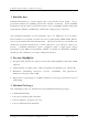
PePLink PolePoint 200BG / 400BG User Manual 1 Introduction PePLink PolePoint is a carrier-grade 802.11b/g Wi-Fi access point. It is a powerful solution for building wholesale wireless networks. Each PePLink PolePoint is loaded with essential features such as Multiple SSID (virtual AP with distinct ESSID and BSSID), VLAN and a high-power antenna One PePLink PolePoint can masquerade up to 16 different access points. Each virtual access point can have its own security policy (WEP, WPA, WPA2, 802.
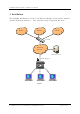
PePLink PolePoint 200BG / 400BG User Manual 4 Installation The PePLink PolePoint is acted as an Ethernet Bridge between the wireless and the Ethernet interface. The network setup is typically like this: WISP 1 WISP 2 WISP 3 Switch Backbone network Radius Server VLAN Tagged LAN Status Wi-Fi Pow er PePLink PolePoint Figure 1 Copyright © 1999-2006 PePLink Ltd.
PePLink PolePoint 200BG / 400BG User Manual 4.1 Procedures • Attach the antenna to the PePLink PolePoint unit. • Connect its LAN port with the backbone network using either a straight-through or cross-over cable. • Plug the power adapter to a power socket and also the power input jack on the unit. • Wait until the status LED turns green • Connect a PC to the backbone network, configure its IP address to be any IP address between 192.168.0.4 to 192.168.0.254 with subnet mask of 255.255.255.
PePLink PolePoint 200BG / 400BG User Manual 4.2 Quick Start With the default settings, an SSID is predefined, which is “PePLink_XXXX” where XXXX is the last 4 digits of the MAC Address. It has both encryption and VLAN tagging off. It bridges the wireless clients to the Ethernet port. So you may now access the Ethernet by associating to it with a Wi-Fi client.
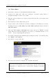
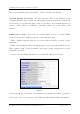
PePLink PolePoint 200BG / 400BG User Manual 5 Configurations 5.1 WLANs Settings Most of Wi-Fi related parameters are configurable in the “WLANs Settings” page accessible from the left side bar. The page is like this: The column “WLAN SSID” shows the virtual APs’ SSID. Figure 5 “Default VLAN ID” is the VLAN ID to be tagged on all outgoing packets (leave from the LAN port) generated from the virtual AP.
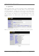
PePLink PolePoint 200BG / 400BG User Manual To modify a virtual AP’s setting, click the link “Edit” on the right of a WLAN SSID. Then you should see: Figure 6 Enable: select Yes to enable the virtual AP, select No to disable the virtual AP. The default is Yes. WLAN SSID: the virtual APs’ SSID. It is the SSID to be scanned by Wi-Fi clients. This value is case insensitive. The substring “####” in the SSID will be replaced by the last four digits of the BSSID / MAC address.
PePLink PolePoint 200BG / 400BG User Manual cannot be hidden from scan. To associate with it, the client should specify the correct ESSID upon association. This is enabled by default. Default Quality of Service: the 802.1p QoS value to be marked to all outgoing packets (leave from the LAN port) generated from the virtual AP. If per-user or per-domain QoS value is specified, the Default Quality of Service value will be overridden. Possible values are Gold, Silver and Bronze.
PePLink PolePoint 200BG / 400BG User Manual IP Start and Stop Range: the IP address range to be offered to DHCP clients Subnet Mask: the subnet mask the DHCP clients to be used Broadcast Address: the broadcast address the DHCP clients to be used Gateway: the default routing gateway the DHCP clients to be used DNS 1, 2 and 3: the DNS servers’ IP address to be offered to the DHCP clients Domain: the domain name the clients to be used Lease Time: the leased of DHCP records Security Policies: to configure the
PePLink PolePoint 200BG / 400BG User Manual 802.1x: to enable 802.1x radius-based authentication with dynamic WEP key. When it is set, the following parameters have to be entered: Figure 9 Key Size: 40bits and 104 bits Broadcast Key Index: 1, 2, 3 or 4 Re-keying Period: Re-keying every this amount of seconds. default is 14400 secs (4 hours). re-keying. The A value of 0 means disable WPA-TKIP / WPA-AES:CCMP: to enable WPA, WPA-PSK, WPA2 or WPA2-PSK. WPA-TKIP is for WPA and WPA-PSK.
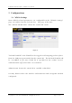
PePLink PolePoint 200BG / 400BG User Manual After finished to modify the settings, press the “Save” button to make the changes effective. Figure 11 5.2 SNMP Settings The PePLink PolePoint supports SNMP v1, v2 and v3. The SNMP Server Settings page allows you to configure the SNMP server settings.
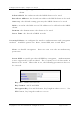
PePLink PolePoint 200BG / 400BG User Manual 5.2.1 SNMPv1/v2 Communities Community Name: the “password” for getting or setting SNMP values. IP Address and IP Mask: the allowed subnet address who can access the SNMP server Access Mode: choose the community name. & Write”. Either “Read Only” or “Read Status: Enable or disable this community. Figure 13 Copyright © 1999-2006 PePLink Ltd.
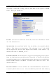
PePLink PolePoint 200BG / 400BG User Manual 5.3 Web Admin Settings In the Web Admin Settings section, you are allowed to change the management web site’s parameters. 5.3.1 Change Management Port Port: The TCP port number of the secure web server. The default is 443. Figure 14 5.3.2 Change Admin Password New Password/New Password (Retype): to enter the new password for entering this Web Admin Interface. Figure 15 Copyright © 1999-2006 PePLink Ltd.
PePLink PolePoint 200BG / 400BG User Manual 5.3.3 Disable Web Administration The web administration interface can be disabled here. again by using SNMP. It can be turned on Figure 16 5.4 Message Log System message log is available. It is a good source of system status during troubleshooting. The message log page can be accessed from the “Message Log” section. Copyright © 1999-2006 PePLink Ltd.
PePLink PolePoint 200BG / 400BG User Manual 5.5 Commands This section allows you to perform some system commands. Figure 16 - Save Current Configuration to Flash – The changes made are not saved to the flash. The configurations will be lost after reboot.
PePLink PolePoint 200BG / 400BG User Manual some debugging information. With the file, PePLink officers are able to get the running status of the PolePoint unit. - Reboot AP – This option is for rebooting the PolePoint unit. 6 Per-session based VLAN tagging The PePLink PolePoint supports VLAN tagging on per-client-session basis when 802.1x authentication is performed. The VLAN ID can be passed from the radius server.
PePLink PolePoint 200BG / 400BG User Manual 7 Appendix A - FAQ Q. How can I restore the system to factory settings? I cannot find such option in the web admin interface. A.
PePLink PolePoint 200BG / 400BG User Manual 8 Appendix B – Radius Server Setup The system has been proved to work with Radiator version 3.9, using EAP-TTLS protocol. PePLink PolePoint settings: Set the virtual Access Point’s authentication protocol to WPA-AES:CCMP.
PePLink PolePoint 200BG / 400BG User Manual 9 Appendix C – Professional Installation Outdoor PolePoint 200/400BG requires professional installation. It is not to be installed by the general public. You must be a Professional Installer. You must follow Part 15 of the FCC rules, and specifically Part 15.203 pertaining to antenna requirements of an intentional radiator. If you are not a professional installer, STOP. Do not proceed any further with the installation.