IUH-F192-V1-* Read/Write Head for IDENTControl Manual
With regard to the supply of products, the current issue of the following document is applicable: The General Terms of Delivery for Products and Services of the Electrical Industry, published by the Central Association of the Electrical Industry (Zentralverband Elektrotechnik und Elektroindustrie (ZVEI) e.V.) in its most recent version as well as the supplementary clause: "Expanded reservation of proprietorship" Worldwide Pepperl+Fuchs Group Lilienthalstr.
IUH-F192-V1-* Contents 1 2 3 Introduction................................................................................................................ 6 1.1 Content of this Document ............................................................................. 6 1.2 Target Group, Personnel ............................................................................... 6 1.3 Symbols Used ................................................................................................
IUH-F192-V1-* Contents 3.4 General Functions and Features ................................................................20 3.5 Indicators and Operating Elements ...........................................................21 3.6 Connection ...................................................................................................21 3.7 Scope of Delivery .........................................................................................22 3.8 Accessories ..............................
IUH-F192-V1-* Contents 7 Service and Maintenance ....................................................................................... 58 8 Troubleshooting....................................................................................................... 59 9 Appendix .................................................................................................................. 60 Dimensions...................................................................................................
IUH-F192-V1-* Introduction 1 Introduction 1.1 Content of this Document This document contains information required to use the product in the relevant phases of the product life cycle.
IUH-F192-V1-* Introduction 1.3 Symbols Used This document contains symbols for the identification of warning messages and of informative messages. Warning Messages You will find warning messages, whenever dangers may arise from your actions. It is mandatory that you observe these warning messages for your personal safety and in order to avoid property damage. Depending on the risk level, the warning messages are displayed in descending order as follows: Danger! This symbol indicates an imminent danger.
IUH-F192-V1-* Certificates and approvals 2 Certificates and approvals 2.1 Declaration of Conformity (RE Directive 2014/53/EU) This product was developed and manufactured under observance of the applicable European standards and guidelines. Note A Declaration of Conformity can be requested from the manufacturer or downloaded from www.pepperl-fuchs.com. The product manufacturer, Pepperl+Fuchs SE, 68307 Mannheim, has a certified quality assurance system that conforms to ISO 9001. ISO9001 2.
IUH-F192-V1-* Certificates and approvals 2.3 IC-Information This device complies with Industry Canada licence-exempt RSS standard(s) and with part 15 of the FCC Rules. Operation is subject to the following two conditions: 1. this device may not cause interference, and 2. this device must accept any interference, including interference that may cause undesired operation of the device. Le présent appareil est conforme aux CNR d'Industrie Canada applicables aux appareils radio exempts de licence.
IUH-F192-V1-* Product Description 3 Product Description 3.1 RFID Frequency Bands 0,1 LF • • • • UHF general 3.2.1 Advantages of UHF 3.2.2 10 HF 100 5,8 GHz 2,45 GHz 1000 UHF MW 10000 Frequency [MhZ] 100 kHz … 135 kHz: low frequency LF 13.56 MHz: high frequency HF 865 MHz … 868 MHz (Europe), 902 MHz … 928 MHz (USA), 920 MHz … 925 MHz (China): ultra-high frequency UHF 2.45 GHz and 5.8 GHz: microwave MW 3.
IUH-F192-V1-* Product Description 3.2.3 Tag Memory Structure User Data TID Bank 11 USER Manufacturer Bank 10 TID Electronic Product Code Bank 01 UII/EPC Protocol Control Bank 00 RESERVED CRC Memory Bank Memory Type Access Password Kill Password Memory Blocks The memory of an EPC Gen2 (ISO/IEC 18000-63) tag is split into four memory banks.
IUH-F192-V1-* Product Description • • 4 bytes: Tag part number • 1 byte: Marking • 12 bits: Tag Mask Designer Identifier (MDID) • 12 bits: Tag model number (TMN), defined by the manufacturer 4 or 8 bytes: Tag serial number Depending on the manufacturer, the serial numbers do not have to be unique or may even be omitted. Bank 11: User memory Bank 11 contains a memory that the user can freely access. The size of this memory depends on the chip type, or this memory may not be present. 3.2.
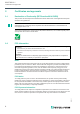
IUH-F192-V1-* Product Description 100 % 90 % 80 % 70 % 60 % 50 % 40 % 30 % 20 % Foam material Film Cardboard (dry) Cardboard (wet) Wood (dry) Glass Metal 10 % al s Material underground M et as Gl Ca Fi rd lm bo ar d Ca (d rd ry bo ) ar d (w et ) W oo d (d Fo ry am ) m at er ial Ai r 0% Material between transponder and read / write device Figure 3.1 3.2.
IUH-F192-V1-* Product Description 3.2.7 Frequency Hopping Spread Spectrum With FHSS (Frequency Hopping Spread Spectrum), the information to be transmitted is distributed successively through multiple channels. Only one frequency channel is used at any one time. This results in a larger bandwidth for the entire signal, in spite of the fact that each channel has a smaller bandwidth. In this section the channel assignment for China and the USA is shown graphically.
IUH-F192-V1-* Product Description 3.3 Countries of Use Note Country Identifier All IUH-F192-V1-* read/write heads operate within their maximum frequency range with the appropriate settings for the relevant country. You must set the correct country identifier when commissioning for the first time. See chapter 5.2.
IUH-F192-V1-* Product Description • • • • • 3.3.4 Radiated power: 10 mW … 4000 mWEIRP; Default = 800 mWEIRP (IUH-F192-V1-FR2) Channel bandwidth: 500 kHz Channel spacing: 500 kHz Frequency access method: frequency hopping spread spectrum. See chapter 3.2.7. Number of channels: 12 Channels used: 1, 2, 3, ... 12 Center frequencies: 919.75 MHz + (M x 0.5) MHz All 12 channels are always used. Brazil In Brazil, the use of RFID in the UHF range is regulated as follows: • • • • • • 3.3.
IUH-F192-V1-* Product Description • • 3.3.9 Frequency access method: programmable frequency list Number of predefined channels: 10 Programmable channels: 1, 2, 3, ... 10 Center frequencies: 865.1 MHz, 865.3 MHz, 865.5 MHz, 865.7 MHz, 865.9 MHz, 866.1 MHz, 866.3 MHz, 866.5 MHz, 866.7 MHz, 866.9 MHz Up to ten channels can be parameterized and used in sequence. Default: dense reader mode on channel 1, 7, 4, 10. See chapter 3.2.6.
IUH-F192-V1-* Product Description 3.3.13 Mexico The regulations for the UHF frequency range in Mexico are the same as the regulations for the UHF frequency range in the USA. See chapter 3.3.19. 3.3.14 New Zealand In New Zealand, the use of RFID in the UHF range is regulated as follows: • • • • • • 3.3.15 UHF frequency range: 921.
IUH-F192-V1-* Product Description • 3.3.17 Number of channels: 10 Channels used: 1, 2, 3, ... 10 Center frequencies: 919.75 MHz + (M x 0.5) MHz All ten channels are always used. South Korea In South Korea, the use of RFID in the UHF range is regulated as follows: • • • • • • 3.3.18 UHF frequency range: 917.2 MHz … 920.
IUH-F192-V1-* Product Description 3.4 General Functions and Features IUH-F192-V1-FR* Figure 3.5 Functions The read/write head was developed for reading and writing passive read/write tags with an ultra-high operating frequency. Detection Range The detection range is typically 4 meters. Tags that comply with EPC Gen 2 (ISO/IEC 1800063) are supported. Maximum Frequency Range The IUH-F192-V1-FR1 read/write head can be operated in the frequency range from 865 MHz to 868 MHz.
IUH-F192-V1-* Product Description 3.5 Indicators and Operating Elements The IUH-F192-V1-* read/write head has 2 x 3 LEDs, which are green/blue/yellow. The various indicators denote: • Green LED: Continuously on - Power on Flashing - Region code must be set. See chapter 5.2. Yellow LED: Read/write operation successful Blue LED: Transmission mode • • 3.6 Connection Caution! Cable specifications The maximum permissible temperature of the connection cable must be at least +80 °C.
IUH-F192-V1-* Product Description 4 Data input/output B, RS-485, -7 V ... +12 V 5 Data output 0 … 3.3 VDC Ground connection The ground connection of the read/write head is positioned on the right-hand side when viewed from the front, if the cable outlet is facing downward. The ground conductor is screwed to the housing with a crimp connector. In order to guarantee safe grounding, mount the serrated washer between the crimp connectors and the housing.
IUH-F192-V1-* Product Description Interface Designation 4 read/write heads: Ethernet IC-KP-B17-AIDA1 2 read/write heads: PROFIBUS IC-KP2-2HB6-V15B Ethernet IC-KP2-2HB17-2V1D EtherCAT IC-KP2-2HB21-2V1D Serial IC-KP2-2HRX-2V1 1 read/write head: PROFIBUS IC-KP2-1HB6-V15B IC-KP2-1HB6-2V15B Ethernet IC-KP2-1HB17-2V1D Serial IC-KP2-1HRX-2V1 Table 3.2 3.8.
IUH-F192-V1-* Product Description 3.8.3 Connection cable for R/W heads and trigger sensors Compatible connection cables with shielding are available for connecting the R/W heads and trigger sensors. Figure 3.8 3.8.
IUH-F192-V1-* Product Description 3.8.5 Installation accessories Two different mounting brackets are available to mount the read/write head on a wall or pole. Figure 3.
IUH-F192-V1-* Installation 4 Installation 4.1 Storage and Transportation Keep the original packaging. Always store and transport the device in the original packaging. Store the device in a clean and dry environment. The permitted ambient conditions must be considered, see datasheet. 4.2 Unpacking Check the product for damage while unpacking. In the event of damage to the product, inform the post office or parcel service and notify the supplier.
IUH-F192-V1-* Installation Mounting the read/write head Figure 4.1 4.3.1 Room Orientation The alignment of the read/write tag antennae in relation to the antennae of the read/write device influences the detection range of the system. Make sure the antennae are aligned parallel to each other.
IUH-F192-V1-* Installation 4.3.2 Minimum Distances When positioning the read/write device, please observe the minimum distances. The lateral distance between the read/write device and metals or liquids should be at least 50 cm. The distance between the read/write device and the ground should be at least 50 cm. > 50 cm metal carrier > 50 cm Read / write device Figure 4.
IUH-F192-V1-* Installation Figure 4.3 1 = Vertical polarization plane 2 = Horizontal polarization plane 4.4 Connection Connect the IUH-F190-V1-* read/write head to the IDENTControl control interface using a shielded cordset (see chapter 3.8.3). Ensure that the shield fully encapsulates the connection cable to avoid EMC interference. (see chapter 4.5) Connect the IUT-F190-R4-V1-* read/write head to the higher level control unit using a shielded cordset.
IUH-F192-V1-* Commissioning 5 Commissioning 5.1 Definitions 5.1.1 Display Angle brackets contain the abbreviated meaning of a command structure, e.g., The index hex or .xx denotes a hexadecimal number. hexASCII denotes a value in the hexadecimal system, specified in ASCII characters. Example: 10dec corresponds to Ahex; A ASCII corresponds to 41hex. see chapter 9.
IUH-F192-V1-* Commissioning 5.2 : Word start address in the read/write tag, 4 hexASCII characters, range from "0000h" to "FFFF", depending on tag type : Number of words to be read or written, 2 hex ASCII characters. Range from "01" through "20" depending on the tag type, word lengths are 4 bytes Initial Commissioning Note Transmission License A country-specific transmission license is required to operate the read/write head.
IUH-F192-V1-* Commissioning Country identifiers for IUH-F192-V1-FR1 (The currently valid transmission licenses can be found in the data sheet at pepperlfuchs.com) Country Identifier Occupied Frequency Bandwidth Frequency Access Method Country or Region 01 865.6 MHz – 867.6 MHz Parameterizable frequency list EU and other countries subject to EN 302208 04 865.0 MHz – 867.0 MHz Parameterizable frequency list India 05 866.0 MHz – 868.0 MHz Parameterizable frequency list Singapore, Vietnam 06 866.
IUH-F192-V1-* Commissioning 5.3 Sensor Settings Warning! Device not configured or configured incorrectly Configure the device prior to commissioning. A device that has not been configured or configured incorrectly may lead to faults in the plant. Warning! L'appareil non configuré ou mal configuré Configurez l'appareil avant de l'utiliser. Un périphérique mal configuré peut provoquer des erreurs dans le système.
IUH-F192-V1-* Commissioning Reading Tags Enhanced Read Read-Only Code Send the enhanced read read-only code command to the read/write head. The "RF ON" LED on the read/write head lights up blue. Serial Ethernet PROFIBUS/PROFINET Command: EF1 .00.04.1D.03 .1D.03 Confirmation: - .00.06.1D.03.FF.0B .1D.03.FF.0B Response: .35.31 .00.06.1D.03.05.0C .1D.03.05.0C Table 5.1 Enhanced read read-only code, no tag in the detection range Move a tag into the read/write head's detection range.
IUH-F192-V1-* Commissioning Single Read Special Read-Only Code As confirmation, read out the read-only code of the tag within the read/write head's detection range via the single read special read-only code command. See "Single Read Special ReadOnly Code SS" on page 38. Serial Ethernet PROFIBUS/PROFINET Command: SS10 .00.04.0A.02 .0A.02 Confirmation: - .00.06.0A.02.FF.30 .0A.02.FF.30 Response: .30.31.00.0E.30. 00.30.14.F7.33.7 C.00.1F.00.00.03 .1C.6E .46.31.30.30.30.3 1 .00.16.0A.02.00.31.00.
IUH-F192-V1-* Operation 6 Operation 6.1 General The sections below contain information about the commands that relate to your read/write head. The commands are described using the example of an IDENTControl control interface with serial interface. All other generally applicable commands and error messages or status messages can be found in the manual for your IDENTControl control interface.
IUH-F192-V1-* Operation 6.3 Command Overview The commands in the list are described in detail on the following pages. The following uses the command syntax for the IUH-F190-V1-* read/write heads with IDENTControl serial control interface. The channel number is always included in the commands. The command syntax is identical to the syntax of the IUT-F190-R4-V1-* read/write heads with integrated RS-485 interface, except for the channel number.
IUH-F192-V1-* Operation 6.4 Read/Write Commands The tag's memory structure is based on the following read/write commands in accordance with EPC Gen 2 (ISO/IEC 18000-63). See chapter 3.2.3. Single Read Read-Only Code SF One attempt is made to read a read-only code (TID). The read-only code is 4, 8, or 12 bytes long, and comprises a 4-byte part number, which denotes the tag type, and optionally a tag with a unique serial number of 4 or 8 bytes. Details see chapter 3.2.3.
IUH-F192-V1-* Operation Enhanced Read Special Read-Only Code ES This command continuously attempts to read the UII segment from tags according to EPC Gen 2 (ISO/IEC 18000-63). If the of a tag is read, this is reported once. If there is no tag in the detection range, or if the tag leaves the measurement range, a status 5 is reported. Command: ES 0 Response: Example: ES10 continuously reads the UII segment.
IUH-F192-V1-* Operation 00000bin No word 0 bits 00001bin One word 16 bits 00010bin Two words 32 bits ... ... ... 11111bin 31 words 496 bits The meaning of the remaining bits is described in EPC Gen 2 (ISO/IEC 18000-63). If a UII/EPC has the length 12 octets, i.e., 6 words (00110bin), and all other bits are equal to 0, the protocol control word corresponds to 00110000 00000000bin or 3000hex. If some of the other bits are not equal to 0, this produces a different protocol control word.
IUH-F192-V1-* Operation Single Write Words SW One attempt is made to write 32-bit words from the address . Command: SW Response: F 0001 Example: SW1000101ABCD writes the 4-byte-long word "ABCD" from memory address "0001". Note The memory bank (MB) parameter defines the bank accessed by this command.
IUH-F192-V1-* Operation Kill UHF Tag KI This command sets a UHF tag to a state where no further access is possible. The command can be executed only if a valid password has previously been set in segment Bank 00 via the command SW. See chapter 3.2.3. The password must have at least 1 non-zero bit. Command: KI .30.
IUH-F192-V1-* Operation Meaning of Bits Command FI = Command 1 = Channel 1 0 = First filter used, filter number = 0 1 = Memory bank 01; should be filtered to UII/EPC 0 = Not negated 0 = OR link not relevant here because only one filter is set 0 0 = Value is always 0 0010 = Start address 10hex or bit 16 28 = Mask length, 28hex = 40dec, i.e., 40 bits 34.00.E2.00.
IUH-F192-V1-* Operation Activate/Deactivate Filter MF Command MF activates or deactivates the filter masks.
IUH-F192-V1-* Operation Command MF - Mode 2 In total, there are 15 tags in the measurement range of the read/write head, with three groups of five marked as either A, B, or C. The filter is set to "B" by command FI. If you execute command MF12 (Activate Filter - Mode 2), this command affects all subsequent commands. If a write command is executed next, all tags in the measurement range that are not "B" tags are selected. These tags are assigned a 'Selected' flag.
IUH-F192-V1-* Operation 6.6 Configuration Commands The response to a configuration command is a status message from the read/write device. During the read operation, a status message and the corresponding data are received as the response. 6.6.1 ChangeTag Command This command tells the R/W system with which tag type to communicate.
IUH-F192-V1-* Operation 6.6.
IUH-F192-V1-* Operation Read Parameters The RP command reads configuration parameters from the read/write head. Command: RP Response: = UASCII for IUH-* = 2 bytes ASCII = Length of in command, 2 bytes binary = Optional additional information Example: RP1UE5.00.00 outputs the number of unsuccessful read attempts until status 5.
IUH-F192-V1-* Operation CD Transmission Channels Programmable frequency list frequency access method: This parameter sets the number and sequence of transmission channels or reads out the number and sequence of transmission channels. Frequency hopping spread spectrum frequency access method: This parameter reads out the number and sequence of transmission channels for the frequency hopping spread spectrum. ParamTyp: CD Default: Depends on the country identifier set, see chapter 3.3.
IUH-F192-V1-* Operation Response: 0 Output Additional Information, "Information" IF Parameter IF allows you to output additional information providing that the reading was successful and the multiframe protocol is activated. See "Protocol Mode QV" on page 53. The additional information is the RSSI value of the reading, the transmission channel used, and transmitting power of this reading.
IUH-F192-V1-* Operation Retrieve Additional Information MD This parameter allows you to retrieve information about the last successful tag access. This returns the RSSI value with a length of 1 byte, the transmission channel used with a length of 1 byte, and the transmitting power with a length of 2 bytes. The RSSI value may be between 0 (= low) and 100 (= high). Parameter MD allows the same data to be accessed in the single-frame protocol as is available in the multiframe protocol with parameter IF.
IUH-F192-V1-* Operation Frequency Access Method Parameterizable frequency list: The parameter can be read only. The parameter specifies the number of transmission channels that are set with parameter CD. ParamTyp: NC Default: NC = 4 Value range: 1 … 50 Example: WP1UNC.00.01.02 allows two channels for a read attempt. RP1UNC.00.00 reads out the number of channels set.
IUH-F192-V1-* Operation Note You can operate the IUH-F192-V1-* read/write head only with internally specified transmission power. You can use the command WP1UPT.00.02.xx.xx in the software to enter any transmission power within the specified range of values. The read/write head automatically sets the transmission power to the next lowest value available. Any entries outside the specified value range are returned as errors. Command RP1UPT.00.00 allows you to read out the power value that is currently set.
IUH-F192-V1-* Operation Responses Depending on Protocol Mode QV Parameter QV Single-frame protocol Multiframe protocol Command Responses SS No tag: 5 One tag: 0 Two tags: A No tag: F0000 Two tags: 0 0 F0002 SR, #SR SF No tag: 5 No tag: F0000 Two tags: 0 0 F0002 One tag: 0 Two tags: A SW, #SW No tag: 5
IUH-F192-V1-* Operation Example: WP1UQW.00.01.04 sets the Q value to 4. The read/write head therefore works with 24 = 16 time slots. RP1UQW.00.00 outputs the set Q value. Country Identifier, "Region Code" RC Parameter RC sets a country identifier or reads out the current country identifier. The country identifier consists of two bytes: • • 1. Byte = 00 You can change the country identifier 1.
IUH-F192-V1-* Operation Default Value Parameters Abbreviation Parameter Default value AP Antenna Polarization AP Combined mode (C) CD Transmission Channels Depending on the country-specific settings, E5 Number of unsuccessful attempts up to Status 5 5 FL Read Out Filter Mask No filter set (0) IF Output Additional Information Off (0) MB Memory Bank User Memory (3) MD Retrieve Additional Information MD Not applicable MF Measurement of Reflected Transmission Not applicable Power NC N
IUH-F192-V1-* Operation Number of Attempts "Tries Allowed" TA This parameter sets the permitted number of read or write attempts, or reads out the permitted number of attempts. ParamTyp: TA Default: TA = 1 Value range: 1 ... 255 Example: WP1UTA.00.01.01 permits precisely one attempt (= no repeats) WP1UTA.00.01.03 permits three attempts RP1UTA.00.
IUH-F192-V1-* Service and Maintenance 7 Service and Maintenance 2022-11 The device is designed and constructed to function stable over long periods of time. For this reason, regular cleaning or maintenance is unnecessary.
IUH-F192-V1-* Troubleshooting 8 Troubleshooting Problem Solution Interference from several read/write heads in the direct vicinity • Change the setting of the transmission channels • Reduce the transmission power Status A message • Check whether there are multiple tags in the detection range: Remove the tag from the detection range by placing the tag in a sealed metal container Repeat the read or write operation • Use filter commands • Determine whether multiple tags have the same UII/EPC •
IUH-F192-V1-* Appendix 9 Appendix 9.1 Dimensions IUH-F192-V1-* 270 81 ø 6.5 (4x) 240 268 247 44 238 Figure 9.
IUH-F192-V1-* Appendix 9.3 hex dec ASCII hex dec 18 24 CAN 38 56 19 25 EM 39 1A 26 SUB 1B 27 ESC 1C 28 1D 1E 1F ASCII hex dec ASCII hex dec ASCII 8 58 88 X 78 120 x 57 9 59 89 Y 79 121 y 3A 58 : 5A 90 Z 7A 122 z 3B 59 ; 5B 91 [ 7B 123 { FS 3C 60 < 5C 92 \ 7C 124 | 29 GS 3D 61 = 5D 93 ] 7D 125 } 30 RS 3E 62 > 5E 94 ^ 7E 126 ~ 31 US 3F 63 ? 5F 95 _ 7F 127 DEL Detection Range The read/write head has a typ
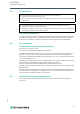
IUH-F192-V1-* Appendix Antenna Diagram The antenna diagrams show the electric field strength in the far field depending on the direction. The front of the read/write head points towards 0°. IUH-F192-V1-FR1 (865 MHz... 868 MHz) and IUH-F192-V1-FR2 (902 MHz... 928 MHz) Horizontal Cut1 -180 0 dB 150 -150 -3 dB -6 dB -9 dB 1 -12 dB -120 120 -15 dB 2 -18 dB -21 dB -24 dB -27 dB 90 -90 -30 dB 60 -60 30 -30 0 1.
IUH-F192-V1-* Appendix Vertical Cut1 -180 0 dB 150 -150 -3 dB -6 dB -9 dB 1 -12 dB -120 120 -15 dB 2 -18 dB -21 dB -24 dB -27 dB -90 -30 dB 90 60 -60 -30 30 0 1. Read/write head points towards 0° 1 - Horizontal polarization 2 - Vertical polarization 2022-11 Figure 9.
Pepperl+Fuchs Quality Download our latest policy here: www.pepperl-fuchs.com/quality www.pepperl-fuchs.