CONTENTS SAFETY PRECAUTIONS ..................................................................................... 2 IMPORTANT SAFETY INSTRUCTIONS ...............................................................4 NORMAL SOUNDS .............................................................................................. 5 AIR CONDITIONER FEATURES..........................................................................5 INSTALLATION INSTRUCTIONS ...............................................................
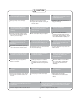
SAFETY PRECAUTIONS To prevent injury to the user or other people and property damage, the following instructions must be followed. Incorrect operation due to ignoring of instructions may cause harm or damage. The seriousness is classified by the following indications. ! ! ! WARNING This symbol indicates the possibility of death or serious injury. CAUTION This symbol indicates the possibility of injury or damage to property. Meanings of symbols used in this manual are as shown below.
! CAUTION ! ! When removing air filter, do not touch metal parts of the unit. Do not clean with water. Doing so may cause an injury. . Water may enter the unit and degrade the insulation causing an electric shock. Unit and Circuit breaker/fuse must be switched OFF when cleaning. Do not put a pet or house plant where it will be exposed to direct air flow. Cleaning unit when power is ON may cause fire and electric shock and may cause an injury. This could injure the pet or plant.
IMPORTANT SAFETY INSTRUCTIONS NOTE The power supply cord with this air conditioner contains a current detection device designed to reduce the risk of fire. Please refer to the section "Operation of Current Device" (below) for details. In the event that the power supply cord is damaged, it MUST be replaced by an authorized repairman. DO NOT, under any circumstances, cut, remove, or bypass grounding prong.
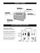
NORMAL SOUNDS High Pitched Chatter High efficiency compressors may have high pitched chatter during the cooling cycle. Vibration Unit may vibrate and make noise because of poor wall or window construction or incorrect installation. Sound of Rushing Air At the front of the unit you may hear the sound of rushing air being moved by the fan. Pinging or Switching Droplets of water hitting condenser during normal operation may cause “pinging” or “switching” sounds.
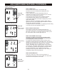
AIR CONDITIONER FEATURES (CONTINUED) NOTE: The following instructions represent the Unit Controls. The same instructions can be used for the Remote Control. TOTEMP/TIMER TURN UNIT ON: Check Filter Sleep TEMP/TIMER on NOTE: The unit will automatically initiate the Energy Saver function under “Cool,” “Dry” and “Auto” (only Auto-Cooling and Auto-Fan) modes. Follow Me off DO THIS: Press the On/Off button.
AIR CONDITIONER FEATURES (CONTINUED) NOTE: MODE button To choose operating mode, press the “Mode” button. Each time you press the button, a mode is selected in a sequence that goes from “Auto,” “Cool,” “Dry,” “Heat,” (for units with heating function) and “Fan.” The indicator light will be illuminated and remain on once the mode is selected. The unit will automatically initiate the Energy Saver function under “Cool,” “Dry,” and “Auto” (only Auto-Cooling and Auto-Fan) modes.
AIR CONDITIONER FEATURES (CONTINUED) TIMER: AUTO START/ STOP FEATURE: TEMP/TIMER Clean Air DO THIS: Press “Timer” button Energy Saver TEMP/TIMER on Auto Cool off Mode Dry Timer Fan CHECK FILTER FEATURE: DO THIS: TEMP/TIMER Sleep Check Filter TEMP/TIMER on Follow Me off Press “Check Filter” button Auto High Fan On/off NOTE: TIMER button First press the “Timer” button. The indicator light beside the word “On” will illuminate indicating the Auto Start program is on.
ADDITIONAL THINGS YOU SHOULD KNOW The Cool circuit has an automatic 3 minute time delayed start if the unit is turned off and on quickly. After unit is turned off, leave unit off for a minimum of 3 minutes before attempting to turn back on. This prevents overheating of the compressor and possible circuit breaker tripping. The fan will continue to run during this time. The control is capable of displaying temperature in degrees Fahrenheit or degrees Celsius.
INSTALLATION INSTRUCTIONS (CONTINUED) Items in Kit You may not need all parts in the kit. Discard unused parts.
INSTALLATION INSTRUCTIONS (CONTINUED) 3. If not existing, drill a 1/8” clearance hole for grounding screw through left side of sleeve, in a clear area about 3 inches maximum (to suit) back from front edge of sleeve (as shown on right) using grounding screw and toothed washer. Pull loose end of ground wire out front of sleeve, and temporarily bend it down and around lower edge of sleeve. The ground wire will be attached to frame of air 1 conditioner later once it is installed. 3 Max. 3/16 Hole 4.
INSTALLATION INSTRUCTIONS (CONTINUED) Wall Sleeve Brands: #1 Emerson • 15” Deep 4 3 8 8 3 4 1. Remove existing rear grille as shown on page 11 of this manual and replace with provided louvered panel. Install as shown here. Note: You may need to drill holes in flange of existing sleeve to match new rear grille. 2. Attach (1) 1” x 3/8” x 25” long seal in the center at the top of the sleeve. Remove the backing paper and press into position. 2 4 4 3.
INSTALLATION INSTRUCTIONS (CONTINUED) Wall Sleeve Brands: #2 Fedders • 19¾” Deep 4 3 8 8 3 4 1. Remove existing rear grille as shown on page 11 of this manual and replace with provided louvered panel. Install as shown here. Note: You may need to drill holes in flange of existing sleeve to match new rear grille. 2. Attach (2) 4½” x 3½” x 1½” centering/support blocks, one on each side wall. Place in center of side walls with the tapered end facing the opening. 3.
INSTALLATION INSTRUCTIONS (CONTINUED) Wall Sleeve Brands: #3 Fedders or Friedrich • 16¾” Deep 4 3 8 8 3 4 1. Remove existing rear grille as shown on page 11 of this manual and replace with provided louvered panel. Install as shown here. Note: You may need to drill holes in flange of existing sleeve to match new rear grille. 2. Attach (2) 4½“ x 3½” x 1½” centering/support blocks, one on each side wall. Place in center of side walls with the tapered end facing the opening. 3.
INSTALLATION INSTRUCTIONS (CONTINUED) Wall Sleeve Brands: #4 General Electric or Hotpoint • 16 7/8” Deep 4 3 8 8 4 3 1. Remove existing rear grille as shown on page 11 of this manual and replace with provided louvered panel. Install as shown here. Note: You may need to drill holes in flange of existing sleeve to match new rear grille. 2. Cut (2) 17” Tapered Spacer Blocks as shown below into two pieces. 17 3/4 Tapered Spacer Block Cut Here 4 4 5 4 1 13 Protection Paper Backing 3.
INSTALLATION INSTRUCTIONS (CONTINUED) Wall Sleeve Brands: #5 Sears or Carrier 51S Series • 18 5/8” Deep 4 3 8 8 3 4 1. Remove existing rear grille as shown on page 11 of this manual and replace with provided louvered panel. Install as shown here. Note: You may need to drill holes in flange of existing sleeve to match new rear grille. 2. Install (2) tapered spacer blocks to the floor of the sleeve as shown. DO NOT CUT THE BLOCKS. This helps induce a rearward slope on the unit. 4 4 5 4 3.
INSTALLATION INSTRUCTIONS (CONTINUED) Wall Sleeve Brands: #6 Whirlpool • 17 1/8” Deep 4 3 8 8 3 4 1. Remove existing rear grille as shown on page 11 of this manual and replace with provided louvered panel. Install as shown here. Note: You may need to drill holes in flange of existing sleeve to match new rear grille. 2. Cut (2) 17” Tapered Spacer Blocks as shown below into two pieces. 17 4 4 5 3/4 4 Tapered Spacer Block Cut Here 1 13 Protection Paper Backing 3.
INSTALLATION INSTRUCTIONS (CONTINUED) Wall Sleeve Brands: #7 Whirlpool • 23” Deep 4 4.5” 5 3 8 8 3 4 4” 6 7 14 10 11 9 13 12 1. Remove existing rear grille as shown on page 11 of this manual and replace with provided louvered panel. Install as shown here. Note: You may need to drill holes in flange of existing sleeve to match new rear grille. Because of the increased unit depth, first try dry fitting using methods described below: 2. Place (2) 1” x 1½” x 14” seals against each side. 3.
INSTALLATION INSTRUCTIONS (CONTINUED) Wall Sleeve Brands: #8 Perfect Aire, White Westinghouse, Frigidaire, Carrier 52F Series • 16” & 17½” Deep 4 3 8 8 3 4 1. Remove existing rear grille as shown on page 11 of this manual and replace with provided louvered panel. Install as shown here. Note: You may need to drill holes in flange of existing sleeve to match new rear grille. Because of the increased unit depth, first try dry fitting, using methods described below: 2.
INSTALLATION INSTRUCTIONS (CONTINUED) Wall Sleeve Brands: #9 White Westinghouse, Frigidaire • 22” Deep 4 5 3 4.5” 8 8 3 4 4” 7 6 6 13 9 10 4.5” 8 12 4” 11 1. Remove existing rear grille as shown on page 11 of this manual and replace with provided louvered panel. Install as shown here. Note: You may need to drill holes in flange of existing sleeve to match new rear grille. Because of the increased unit depth, first try dry fitting, using the method described below: 2.
INSTALLATION INSTRUCTIONS (CONTINUED) Direct Unit Mounting The previous directions are the preferable way to mount the new rear grille. The unit’s performance is slightly better and the possibility of drafts is reduced. As a last resort, direct mounting of the grille to the unit can be considered. Note: The grille must be installed prior to inserting the unit into the sleeve. 1. Attach the 2 seal pieces (1” x 3/8” x 14”) as shown in Fig. 1. 2.
INSTALLATION INSTRUCTIONS (CONTINUED) 1. Install the 1” x 1 1/2” x 84” long stuffer-seal between the wall-sleeve and the unit. A flat-bladed screwdriver or putty knife is recommended. 2. Assemble the trim frame by inserting top and bottom pieces into side pieces and snapping into place. 3. Pull cord through trim frame then slide in unit until flush with wall.
CARE AND CLEANING ! CAUTION N Clean air conditioner occasionally to keep it looking and operating like new. Be sure to unplug the unit before cleaning to prevent shock or fire hazards. Air Filter Cleaning The air filter should be cleaned at least every two weeks or as necessary. Trapped particles in the filter can build up and cause an accumulation of frost on the cooling coils. ● Grasp the filter by the center and pull up and out ● Wash the filter using liquid dishwashing detergent and warm water.
TROUBLESHOOTING TIPS Before calling for service, please review the chart below. Issue AIR CONDITIONER NOT COOLING ROOM, OR NOT BLOWING COLD AIR AIR CONDITIONER COOLING BUT ROOM IS TOO WARM - ICE FORMING ON COOLING COIL BEHIND DECORATIVE FRONT AIR CONDITIONER CYCLING ON AND OFF TOO FREQUENTLY OR NOT ENOUGH UNIT WILL NOT TURN ON UNIT BLOWS FUSES OR POPS CIRCUIT BREAKER AIR CONDITIONER IS MAKING NOISES Possible Solutions • Be sure unit is not too large or too small for the area of the room.
Your Source for Home Comfort Distributed by: Perfect Aire, LLC 5151 Belt Line Rd. Suite 878 Dallas, TX 75254 877-365-6274 www.perfectaire.us Specification and performance data is subject to change without notice.