
User Manual


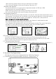


(3) Plug thro tt le serv o connecto r into CH2 channel.
(4) Plug dire cti on servo into CH1 channel.
(5) Instal l 4 AA alkaline batt ery into battery case (or BEC syste m : 4-7 CELL Nicad piles; with out
BEC system: 5 CELL Nicad piles) and connect th e port with th e re ceiver switch interfa ce.
(6) Check wheth er the re ceiver crystal suit with tr ansmitter cry stal .
(7) Turn on th e tr ansmitt er.
(8) Put servo switch on "ON" positi on. (See pictu re 16)
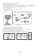
d. Transposing dire ction and ste eri ng wheel positi on
(1). Tweak 4 inner hexagon screws on steeri ng wheel fixer.
(2). Take out steering wheel slightl y and plug out th e pin by pictu re. (See picture 17)
(3). Tweak 4 inner hexagon screws on rear fixing board .
(4). Insert adjusting wheel pin into CH1 socket and fi x th e screw. (See picture 18)
(5). Fix the re ar board on the ste ering wheel position. (See picture 19)
Picture 17
Picture 18
Picture 19
Picture 16